Dear Dr. Jason,
I have a question please, and I hope you could help me.
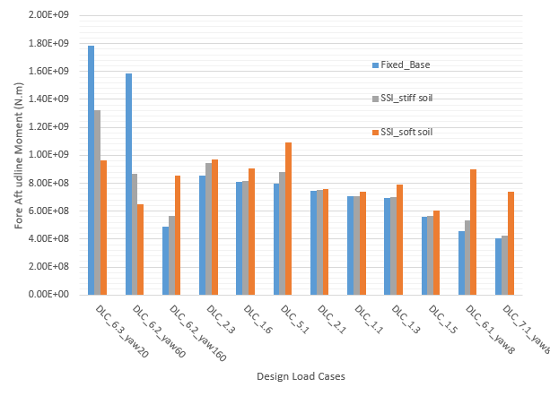
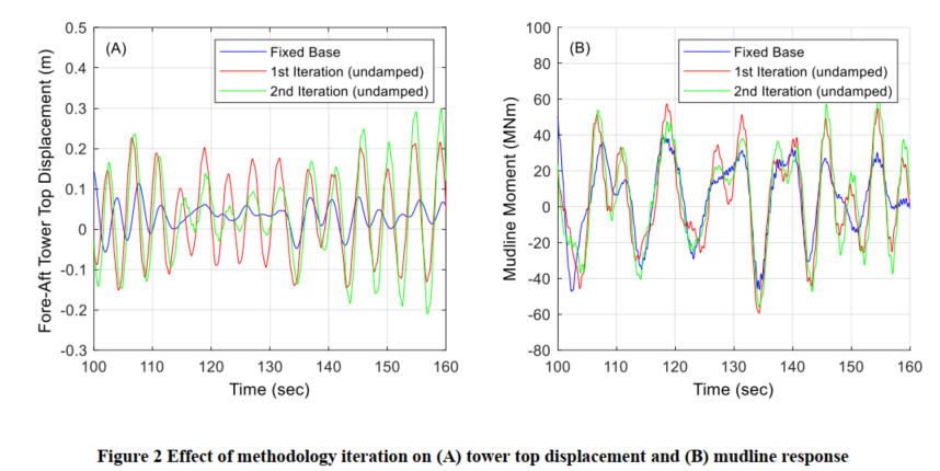
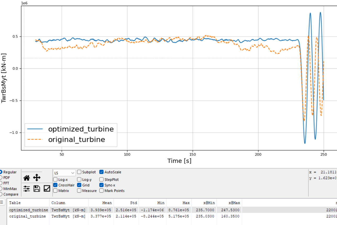
1- I have optimized the structure considering the tower and monopile thickness distribution as well as the embedded pile length, with updates to the mode shapes, cross-sectional properties, and the soil-structure interaction (SSI) stiffness matrix. Following this optimization, the first natural frequency of the turbine was reduced to 0.136 Hz. The difference in dynamic loading before and after these updates is shown in the attached figure:
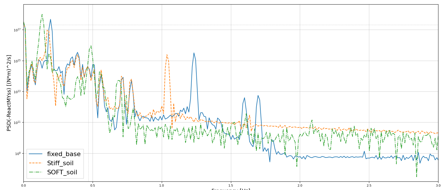
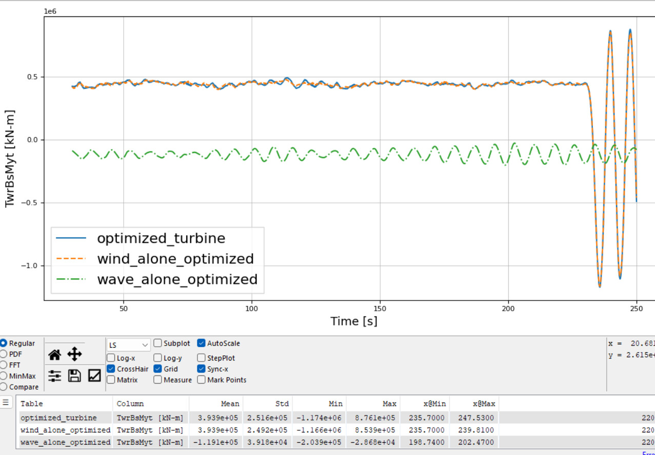
2- To further understand this behavior and investigate the potential for
resonance, I decomposed the environmental loads into
wind-only and
wave-only cases. My objective was to determine whether the increase in loading was primarily driven by
wave excitation, given that the optimized natural frequency is close to typical wave frequencies. The analysis showed that the load increase is
primarily driven by wind rather than wave excitation:
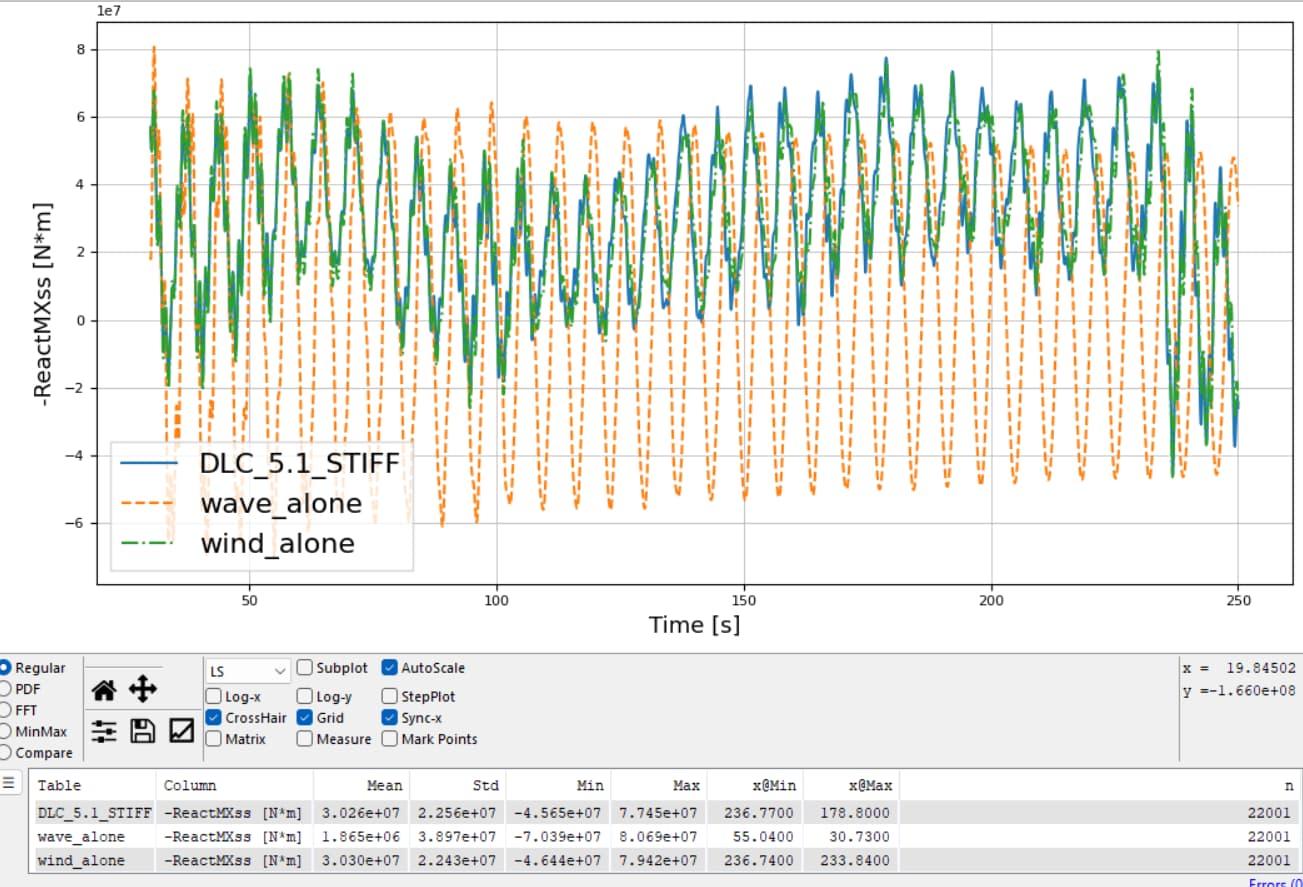
However, the response in the
X-direction still raised concerns:
my question is
1- 1.
Is the observed increase in loading mainly due to resonance effects, or is it more a consequence of the increased
flexibility of the optimized structure, which leads to higher deformations under wind loading?
2.
Is it problematic that the optimized turbine has a natural frequency of
0.136 Hz, which lies within the
range of wave excitation frequencies? Although wave-induced loading is not dominant, is there still a risk?
3.
What are the implications of resonance in such a case, particularly considering that I have imposed constraints on
von Mises stress and
pile head displacements, and the optimized design satisfies those safety criteria? I am aware of the case presented in the report
“Sustainable Installation of XXL Monopiles – Lessons Learned from SIMOX/COAX Offshore Campaign (Tsouvalas et al.)”, where resonance occurred during installation due to the vibro-hammer operating at a frequency matching the monopile’s natural frequency. This led to
local stress amplification,
material degradation, and eventual
cracking and failure.
I would be very grateful for your insight into whether the observed behavior in my model indicates a structural risk or is an acceptable outcome given the design constraints applied.