Dear Dr Jonkman:
My name is Emanuel M. Rergis, and I am a PhD student at the University of Nottingham in the UK. An important part of my PhD project is about the implementation of a PTMD (Pendulum Tuned Mass Damper) with an electrorheological damper inside the nacelle of an offshore wind turbine. For this purpose, I have given myself the task of running several simulations on MAtLab. However, I see that it would be very useful to be able to implement these models that I have already run with all the features and benefits that OpenFAST provides. I am not very familiar with all the functions of the software yet, however, I have read that there are modules called ServoDyn and SubDyn. These modules already have the functions of TMD or LCD predetermined. My question is, faced with all this, what do you recommend I do? How can I start? I am willing to share my results, if during all this process I manage to find relevant information, because it seems that OpenFAST does not have the PMTD function included. Thank you very much and kind regards.
Emanuel M. Rergis
Dear @Emanuel.Rergis,
I would first recommend reviewing the available functionality and theory behind the Structural Control (StC) submodel of ServoDyn to see if these models adequately represent the physics of the PTMD you are trying to model (at least to first-order accuracy)–see the StC documentation here: 4.2.12. Structural Control (SrvD) — OpenFAST v3.4.1 documentation. It would be great to summarize what additional physics needs to be captured for higher accuracy. With that, you can then decide what method is best to address the physics gaps, such as modifying the StC source code or interfacing to a controller or MATLAB/Simulink.
Best regards,
Thank you very much! I’ll take your pieces of advice into consideration. Kind regards!
Dear Dr Jonkman:
It saddens me so much to have to ask you again. I started reading the documentation about TMDs, and I understood that to implement them in openfast I need a submodule called Stc. I downloaded this submodule and pasted it into the folder corresponding to the 5MW_OC3Mnpl_DLL_WTurb_Waveslrr wind turbine model. After that, I updated the .fst file but the simulation didn’t run and caused fatal error. This is the way I did it:
------- OpenFAST EXAMPLE INPUT FILE -------------------------------------------
FAST Certification Test #19: NREL 5.0 MW Baseline Wind Turbine with OC3 Monopile RF Configuration, for use in offshore analysis
---------------------- SIMULATION CONTROL --------------------------------------
True Echo - Echo input data to .ech (flag)
“FATAL” AbortLevel - Error level when simulation should abort (string) {“WARNING”, “SEVERE”, “FATAL”}
60 TMax - Total run time (s)
0.005 DT - Recommended module time step (s)
2 InterpOrder - Interpolation order for input/output time history (-) {1=linear, 2=quadratic}
0 NumCrctn - Number of correction iterations (-) {0=explicit calculation, i.e., no corrections}
99999 DT_UJac - Time between calls to get Jacobians (s)
1E+06 UJacSclFact - Scaling factor used in Jacobians (-)
---------------------- FEATURE SWITCHES AND FLAGS ------------------------------
1 CompElast - Compute structural dynamics (switch) {1=ElastoDyn; 2=ElastoDyn + BeamDyn for blades}
1 CompInflow - Compute inflow wind velocities (switch) {0=still air; 1=InflowWind; 2=external from OpenFOAM}
2 CompAero - Compute aerodynamic loads (switch) {0=None; 1=AeroDyn v14; 2=AeroDyn v15}
1 CompServo - Compute control and electrical-drive dynamics (switch) {0=None; 1=ServoDyn}
1 CompHydro - Compute hydrodynamic loads (switch) {0=None; 1=HydroDyn}
1 CompSub - Compute sub-structural dynamics (switch) {0=None; 1=SubDyn; 2=External Platform MCKF}
0 CompMooring - Compute mooring system (switch) {0=None; 1=MAP++; 2=FEAMooring; 3=MoorDyn; 4=OrcaFlex}
0 CompIce - Compute ice loads (switch) {0=None; 1=IceFloe; 2=IceDyn}
0 MHK - MHK turbine type (switch) {0=Not an MHK turbine; 1=Fixed MHK turbine; 2=Floating MHK turbine}
---------------------- ENVIRONMENTAL CONDITIONS --------------------------------
9.80665 Gravity - Gravitational acceleration (m/s^2)
1.225 AirDens - Air density (kg/m^3)
1027 WtrDens - Water density (kg/m^3)
1.464E-05 KinVisc - Kinematic viscosity of working fluid (m^2/s)
335 SpdSound - Speed of sound in working fluid (m/s)
103500 Patm - Atmospheric pressure ¶ [used only for an MHK turbine cavitation check]
1700 Pvap - Vapour pressure of working fluid ¶ [used only for an MHK turbine cavitation check]
20 WtrDpth - Water depth (m)
0 MSL2SWL - Offset between still-water level and mean sea level (m) [positive upward]
---------------------- INPUT FILES ---------------------------------------------
“NRELOffshrBsline5MW_OC3Monopile_ElastoDyn.dat” EDFile - Name of file containing ElastoDyn input parameters (quoted string)
“…/5MW_Baseline/NRELOffshrBsline5MW_BeamDyn.dat” BDBldFile(1) - Name of file containing BeamDyn input parameters for blade 1 (quoted string)
“…/5MW_Baseline/NRELOffshrBsline5MW_BeamDyn.dat” BDBldFile(2) - Name of file containing BeamDyn input parameters for blade 2 (quoted string)
“…/5MW_Baseline/NRELOffshrBsline5MW_BeamDyn.dat” BDBldFile(3) - Name of file containing BeamDyn input parameters for blade 3 (quoted string)
“…/5MW_Baseline/NRELOffshrBsline5MW_InflowWind_12mps.dat” InflowFile - Name of file containing inflow wind input parameters (quoted string)
“NRELOffshrBsline5MW_OC3Monopile_AeroDyn15.dat” AeroFile - Name of file containing aerodynamic input parameters (quoted string)
“NRELOffshrBsline5MW_OC3Monopile_ServoDyn.dat” ServoFile - Name of file containing control and electrical-drive input parameters (quoted string)
“NRELOffshrBsline5MW_OC3Monopile_HydroDyn.dat” HydroFile - Name of file containing hydrodynamic input parameters (quoted string)
“NRELOffshrBsline5MW_OC3Monopile_SubDyn.dat” SubFile - Name of file containing sub-structural input parameters (quoted string)
“NRELOffshrBsline5MW_StC.dat”
“unused” MooringFile - Name of file containing mooring system input parameters (quoted string)
“unused” IceFile - Name of file containing ice input parameters (quoted string)
---------------------- OUTPUT --------------------------------------------------
True SumPrint - Print summary data to “.sum” (flag)
1 SttsTime - Amount of time between screen status messages (s)
99999 ChkptTime - Amount of time between creating checkpoint files for potential restart (s)
0.05 DT_Out - Time step for tabular output (s) (or “default”)
0 TStart - Time to begin tabular output (s)
0 OutFileFmt - Format for tabular (time-marching) output file (switch) {0: uncompressed binary [.outb], 1: text file [.out], 2: binary file [.outb], 3: both 1 and 2}
True TabDelim - Use tab delimiters in text tabular output file? (flag) {uses spaces if false}
“ES10.3E2” OutFmt - Format used for text tabular output, excluding the time channel. Resulting field should be 10 characters. (quoted string)
---------------------- LINEARIZATION -------------------------------------------
False Linearize - Linearization analysis (flag)
False CalcSteady - Calculate a steady-state periodic operating point before linearization? [unused if Linearize=False] (flag)
3 TrimCase - Controller parameter to be trimmed {1:yaw; 2:torque; 3:pitch} [used only if CalcSteady=True] (-)
0.001 TrimTol - Tolerance for the rotational speed convergence [used only if CalcSteady=True] (-)
0.01 TrimGain - Proportional gain for the rotational speed error (>0) [used only if CalcSteady=True] (rad/(rad/s) for yaw or pitch; Nm/(rad/s) for torque)
0 Twr_Kdmp - Damping factor for the tower [used only if CalcSteady=True] (N/(m/s))
0 Bld_Kdmp - Damping factor for the blades [used only if CalcSteady=True] (N/(m/s))
2 NLinTimes - Number of times to linearize (-) [>=1] [unused if Linearize=False]
30, 60 LinTimes - List of times at which to linearize (s) [1 to NLinTimes] [used only when Linearize=True and CalcSteady=False]
1 LinInputs - Inputs included in linearization (switch) {0=none; 1=standard; 2=all module inputs (debug)} [unused if Linearize=False]
1 LinOutputs - Outputs included in linearization (switch) {0=none; 1=from OutList(s); 2=all module outputs (debug)} [unused if Linearize=False]
False LinOutJac - Include full Jacobians in linearization output (for debug) (flag) [unused if Linearize=False; used only if LinInputs=LinOutputs=2]
False LinOutMod - Write module-level linearization output files in addition to output for full system? (flag) [unused if Linearize=False]
---------------------- VISUALIZATION ------------------------------------------
0 WrVTK - VTK visualization data output: (switch) {0=none; 1=initialization data only; 2=animation; 3=mode shapes}
3 VTK_type - Type of VTK visualization data: (switch) {1=surfaces; 2=basic meshes (lines/points); 3=all meshes (debug)} [unused if WrVTK=0]
false VTK_fields - Write mesh fields to VTK data files? (flag) {true/false} [unused if WrVTK=0]
15 VTK_fps - Frame rate for VTK output (frames per second){will use closest integer multiple of DT} [used only if WrVTK=2 or WrVTK=3]
Could you advise me on what I did wrong, please?
Thanks a lot!
Kind regards.
Dear @Emanuel.Rergis,
The name of the StC input file should be specified within the ServoDyn input file (via ServoDyn input NStCfiles for nacelle-based StC), not listed in the “INPUT FILES” section of the primary OpenFAST (.fst) input file.
Best regards,
Thank you very much, D. Jonkman. I did it just the way you described it, and everything worked well.
Kind regards,
Emanuel M. Rergis
1 Like
Dear @Jason.Jonkman D. Jonkman:
This is me again, bothering you. I’m sorry for that. I have been trying to see where I can control the wind spectra. I need to inject a von Karman and a Kaimal spectra to study the effect of a TMDx in the nacelle and tower displacements, but I don’t manage to see in what line of the AeroDyn15 file this option is.
Could you please advise me on what to do, again?
Have a wonderful day, and many thanks in advance.
Emanuel M. Rergis
Dear @Emanuel.Rergis,
Actually, the wind spectrum is not specifically specified in AeroDyn, or OpenFAST for that matter. The ambient wind data to be used within OpenFAST is specified in the InflowWind module of OpenFAST. But full-field turbulence is specifically defined in a pre-processing step (e.g., using TurbSim), and only the full-field turbulence data file (generated by TurbSim) is specified within InflowWind. Within TurbSim, you can specify the wind spectrum and other atmospheric conditions (such as coherence), as well as the inflow spatial-temporal discretization.
Best regards,
Thank you very much @Jason.Jonkman. I can see what you meant now that I accessed the TubSim file. One more question, if possible, I could notice that the files are written in Fortran code. Can I adjust them directly from the notepad? By the way, I assumed that the files named TurbSim_Types and Velocity_Spectra are the ones to specify the turbulence percentage and the type of spectrum model. Am I right? Please find attached a screenshot of what I am talking about.
Best wishes,
Emanuel M. Rergis
Dear @Emanuel.Rergis,
You should not need to change the TurbSim source code that you are showing, unless you are fixing a bug or want to add functionality not currently supported. I suspect you simply need to use the precompiled TurbSim executable without changing the source code.
The TurbSim input file can be used to set the typical turbulence parameters, including the mean profile, turbulence spectrum, coherence, inflow spatial-temporal discretization etc.
Best regards,
Thanks one more time for this valuable information Dr. @Jason.Jonkman . Now I started to work with the module STC. Unfortunately, it didn’t work as expected. I used the TMD with the values proposed in the paper "Passive structural control of offshore wind turbines" by M.A Lackner et al. and a failure occurred. Could you please advise me on what I should adjust? I’m attaching a screenshot of the corresponding command prompt
Dear @Emanuel.Rergis,
It looks like your OpenFAST model is unstable. Can you isolate what it is you changed in your OpenFAST model to make it unstable? Was it the addition of the TMD model in StC or something else you changed? Does reducing the glue code time step (DT) resolve the issue?
Best regards,
Thank you for your quick reply Dr. @Jason.Jonkman. I just changed the parameters mentioned in the paper I cited. Please, find attached these two screenshots.
Dear @Emanuel.Rergis,
I’m questioning the value of StC_P_Z = 75 m. This is likely OK for a tower-based TMD, but I thought you were implementing a nacelle-based TMD, in which case 75 m above the yaw bearing sounds unrealistic.
Again, does reducing the glue code time step (DT) resolve the issue?
Best regards,
Dear Dr @Jason.Jonkman:
Thanks one more time for your reply. I changed the value of StC_P_Z= 1.5 m and reduced the glue code time step (DT) to almost 100 times its original value. Apparently, the simulation runs fine. How can I detect this kind of problem in the future? Is this because of the stiffness and damping values I chose? I’m trying to follow what M.A Lackner proposed in his paper to study the contribution of the TMD to reducing the tower tip fore-aft and side-to-side displacements.
Kind regards,
Emanuel M. Rergis
Dear @Emanuel.Rergis,
OK, I’m glad you got the model to run now.
There are many posts on this forum that provide guidance on how to select a suitable time step (DT). The time step requirement is dictated by the highest full-system natural frequencies of your model (with the standard rule of thumb being DT < 1/(10*f_max), which will depend on the system masses and stiffness. The full-system natural frequencies (including f_max in Hz) can be found through a linearization analysis followed by eigenanalysis (including MBC3 if the rotor is spinning with blade degrees of freedom enabled). There is also a balance between time step size (DT) and number of correction steps (NumCrctn); smaller DT can likely use smaller (or zero) NumCrctn, but setting NumCrctn to 1 or higher may allow you to use larger DT.
Best regards,
Dear Dr @Jason.Jonkman:
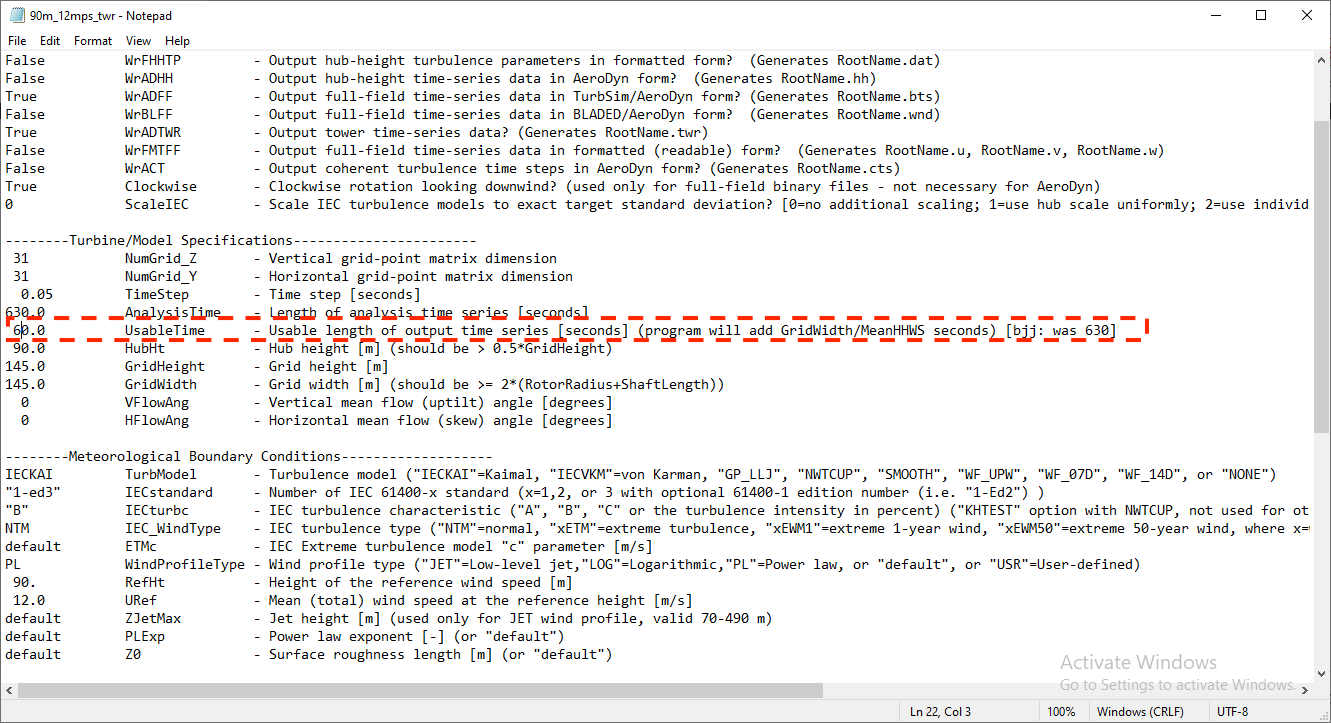
Thank you one more time for your quick response. Now I changed the simulation time to 600s. And I obtained a simulation error. I looked into the forum for further information on this matter and found that my wind files needed to be changed. I’m unsure about what Wind files I should change; that’s why I’m attaching two screenshots of what I understood needed a change. You also mentioned a grid size. Is this the one I show you in my third picture? By the way, I’m simulating an offshore wind turbine. I’m saying this because you pointed out the importance of onshore and offshore wind turbines in electing these parameters.
Thanks a lot for your patience and quick response.
Best regards.
One more question. Is there another way to access this specific information? Maybe a general manual in a PDF version? Does NREL offer any courses on how to understand OpenFAST?
Dear @Emanuel.Rergis,
Your problem is your UsableTime is too short. For a 10-minute (600-s) simulation, I would generally recommend that you set AnalysisTime = 600 s and UsableTime = “ALL”, in which TurbSim will generate a periodic wind data file that repeats every 600 s. This will allow you to run a longer simulation (say 630 s) in OpenFAST and throw away the results during the start up transient (30 s in this example) and still give you 600 s of valid simulation results to post-process.
When using TurbSim with OpenFAST, the wind domain and its spatial-temporal discretization is specified in TurbSim. The section you highlight at the bottom of the InflowWind input file is only used if you use WindType = 5 (HAWC format), which is not used in conjunction with TurbSim.
OpenFAST user documentation is available here: 4. User Documentation — OpenFAST v3.4.1 documentation, but some documentation is more exhaustive than others. The TurbSim documentation is not yet ported to readthedocs, but you can find the prior documentation (mostly up-to-date) here: https://www.nrel.gov/wind/nwtc/assets/downloads/TurbSim/TurbSim_v2.00.pdf.
Regarding OpenFAST workshops, see the following forum topic: Modeling Workshops. Our next public workshop will likely be held in conjunction with the NAWEA / WindTech 2023 conference the last week of October in Colorado.
Best regards,
Dear Dr @Jason.Jonkman:
Thanks again for the feedback and quick response. I changed the parameters you suggested, AnalysisTime = 600 s and UsableTime = “ALL”, but unfortunately, I’m still getting the same simulation error. Is there any other parameter I should change? Am I missing anything?
One more thing, apparently, there is no fully updated OpenFAST user guide manual. I could download just some module user guides separately. I assume this is because of a lack of time for this thorough job. Therefore, I would like to volunteer to transcribe all the information to get a single updated manual. Since I’m a PhD student, I cannot commit to working on it from Monday to Friday, but during the weekend, I can undertake this project and work 8 hours on Saturday and eight on Sunday. So, if this help is needed, please do not hesitate and let me know.
Best wishes,
Emanuel M. Rergis
Dear @Emanuel.Rergis,
After changing AnalysisTime = 600 s and UsableTime = “ALL”, did you rerun TurbSim to generate the updated turbulent wind data file and specify that file within InflowWind? If so, I would not expect that you’d receive the same error you received before.
Thank you for volunteering to contribute to OpenFAST! What you propose sounds extreme, but obviously any help is appreciated. You can see the open OpenFAST issues that we have marked as “Help Wanted” here: Issues · OpenFAST/openfast · GitHub. NREL has slowly been trying to convert all of the prior documentation from FAST v7 and v8 to OpenFAST readthedocs (OpenFAST Documentation — OpenFAST v3.4.1 documentation), which is now our central repository for OpenFAST documentation, but this is happening slower than desired.
Best regards,