Dear NREL-Team,
for the 5MW baseline wind turbine I have carried out investigation of extreme loads.
I used the openFAST (Unversioned from 6d9e2b9f48f619e9a74ee6e501d24d4ef47ec21f). As structure model I used ElastoDyn. The extreme values were determined with MExtrem.
The maximum force in x-direction is DLC 1.3 V_ref=25 m/s and in y-direction is DLC 6.1 (idling turbine).
The Simulation Parameter:
DlC 1.3
V_ref=25 m/s (ETM)
WakeMod 2
AFAeroMod2
TowerPotent 1
PC Mode 5
AzimB1Up 0
In general, this model wasn´t changed from the test files in the regression test.
Azimuth position blade 1 = 208.3°
DLC 1.6
WakeMod 0
AFAeroMod 1
PC Mode 0
AzimB1Up 0
Azimuth position blade 1 = 326°
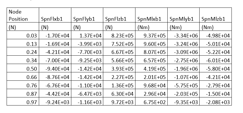
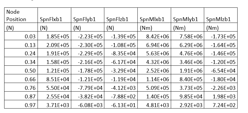
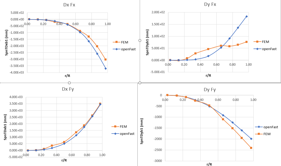
These forces are used for a FE-model of the blade. They are applied via rigid bodies at the pitch axis at the same position in as in openFAST. I wanted to validate the layup of the model by comparing the displacement of the FE-model with the deflection of openFAST. The shown in the figure displacement is taken from the pitch axis.
There are deviations of the deflection I cannot explain ou can see that the displacement calculated by FEM makes sense, but in the openFAST simulation the deflection on y-axis I don´t understand. Do you have any suggestion why there is a change of sign? Am I doing it wrong in my simulation?
My second question is, in which direction the local blade coordinate system is. In my understanding the y-axis of every node is parallel to the chord of the root and not of the chord at the node position? The z-axis is along the pitch axis.
Regards
Moritz
Dear Moritz,
Regarding your second question, the local blade coordinate system in ElastoDyn (Lb1, Lb, LB3 for blades 1, 2, and 3, respectively) accounts for the local structural pretwist and the local deflection of the blade.
A few clarifying questions, which may point to the answer regarding your first question:
- Can I assume the “Node Position” in your tables is a fraction of the blade radius from 0 at the root to 1 at the tip, and so, the units are should say “(-)” instead of “(N)”?
- The local shear forces and bending moments that you are outputting are the local reaction loads at each node along the blade. So, the loads are found by integrating the applied and inertial loads from each node to the tip, and so, accumulate along the blade. How are you applying these loads to your FE model? Perhaps you are apply something like SpnFlxb1(9) at z = 0.97, SpnFlxb1(8) - SpnFlxb1(9) at z = 0.87, etc.? This would, of course, be a rough approximation because you are not taking the local coordinate systems into account.
- How are you accounting for the the structural pretwist of the blade in your FE model?
Best regards,
Dear Jason,
thank you for your answer.
You are right the Node position is a fraction of the blade radius. The unit is a typo.
You are also right, how I applied the loads at the FE-model. According to your answer I should use at least a rotation matrix to take the pre twist into account.
For the FE model I’m accounting the pre twist withe CAD model I’m using. It is designed according to the blade data and with reference to the sandia blade layup.
Best regards
Moritz
Dear Moritz,
OK, hopefully the deflection plots make a bit more sense when you update how you calculate the local applied loads.
Best regards,
Dear Jason,
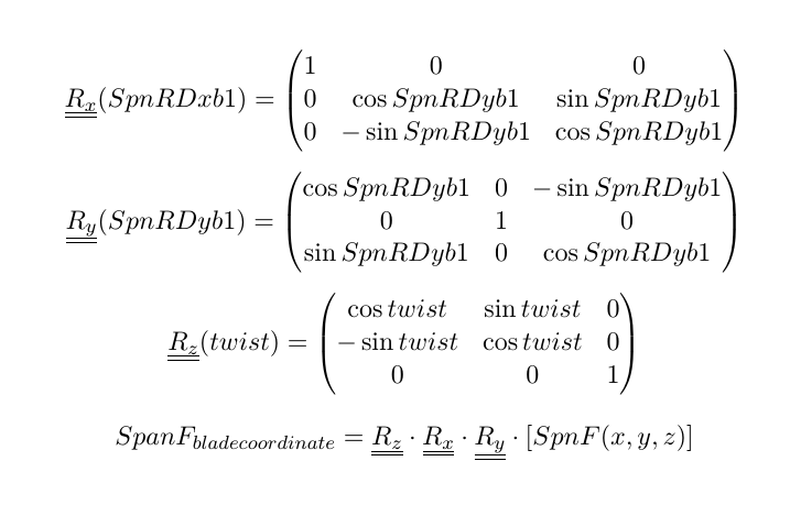
I have transformed the loads with the pretwist and the angle of deflection (SpnRDxbi and SpanRDyb1).
The deflection looks better now. There is still a deviation. However, it could also be due to the fact that the structural properties of the rotor blade are not ideally represented and I have do adjust them.
best regards
Moritz
Hi Moritz,
I’m glad that your results are making a bit more sense to you now.
A few comments on your equations:
- This just appears to be a typo, but R_x() needs to use SpnRDxb1, not SpnRDyb1.
- I believe the signs on the SIN() terms are opposite for R_x() and R_y(), considering that you are using the transformation to go from local to global (blade). The signs of the SIN() terms in R_z() look correct because +twist is defined about -z.
- While the product of R_z()*R_x()*R_y() would be correct for a z-x-y rotation sequence from global (blade) to local, in reality, the ElastoDyn module uses a small angle transformation for the blade deflections. So, instead of R_x()*R_y(), ElastoDyn would use the inverse / transpose of the matrix in Equation (2-2) of the following NREL report: nrel.gov/docs/fy08osti/41958.pdf (where theta_x = SpnRDxb1 and theta_y = SpnRDyb1 in radians and the transpose is needed because the equation as stated goes from global (blade) to local, and you want to go from local to global (blade).
I hope that helps.
Best regards,
Dear Dhaneesh,
Buckling is not directly considered within OpenFAST. Of course, you can post-process the loads output from OpenFAST to calculate the onset of buckling.
As has been discussed several times on this forum (e.g.: Foundation Stiffness and damping in FAST v8), foundation flexibility and soil-structural interaction are not available in the master branch of OpenFAST. That said, NREL has been working on this recently, by both including a 6x6 stiffness matrix (coupled springs model) at joints in SubDyn and by introducing a new module, SoilDyn. SoilDyn provides an option for a simple 6x6 stiffness matrix, but also includes options for interfacing to the REDWIN DLLs developed by NGI (to model soil-structure interaction via a superelement, including soil hysteresis), as well as and a placeholder for future implementation of a p-y and t-z curves. These are not currently included in a public release, but are being developed in branches on forks of OpenFAST.
Best regards,
Sir,
1.Thank you for your information regarding foundation stiffness.
- Are there any Matlab scripts like MBC to post-process the output from OpenFAST to get a response by considering the buckling effect on the turbine?
Thank you.
Dear Dhaneesh,
I’m not aware of any NREL-developed post-processors that include a buckling check, although perhaps this is included in NREL’s WISDEM Systems Engineering tool (github.com/WISDEM), of whose details I am not very familiar with.
Best regards,
Sir,
1.NREL 5MW reference turbine used in FAST/OpenFAST code is a linear model that considers the combination of modal and multi-body dynamics with limited DOF’s. So the output generated by FAST is coupled linear response due to wind-wave loads? Are any nonlinearities considered in the NREL 5MW model?
- In FAST/OpenFAST Can we consider different directionality of wave and wind?
Dear Dhaneesh,
Actually, FAST/OpenFAST contain many nonlinear terms. For information on the FAST theory basis, please see the following forum topic: Coupled blade modes in FAST.
Yes, FAST/OpenFAST can consider different directionality of wind and waves. InflowWind input parameter PropagationDir sets the mean wind direction and HydroDyn input parameter WaveDir sets the mean wave direction.
Best regards,
Sir,
I have used the coupled spring model for platform model 2 in FASTv7 and conducted a nonlinear dynamic analysis for NREL 5MW offshore turbine under the action of seismic, wind& wave. I conducted a fragility analysis and calculated the fragility functions for a displacement damage state for the tower top displacement parameter TTDspFA. Likewise, I want to calculate fragility functions for other damage states such as tower failure i.e, yielding stress for the tower. So Is there a chance to get yield stress or other tower failure representing parameters in fast.
Thank you.
HI Dhaneesh,
FAST considers the mass, stiffness, and the structural response and loading of the tower, but it does not directly calculate tower yield or failure. These analyses are typically done in a post-process of FAST, as has been discussed on this forum before, e.g., search for “yield” or “limit state”.
Best regards,
Sir,
I have seen some of the topics in this forum regarding the damage of tower and monopile. For the monopile supported offshore wind turbine with foundation modeled using coupled springs under the action of combined seismic, wind & wave, does the output parameter TwrBsMyt represents the moment due to coupled seismic, wind&wave forces acting in the fore-aft direction at the seabed? If so I would like to calculate the stress from the bending equation i.e, sigma = (My)/I. Where M= TwrBsMyt & y= outer dia/2 & I = pi/64( D_o^4 - D_i^4 ). And the yield strength of steel based on the grade of steel that was used for NREL 5MW wind turbine tower& monopile. Is this procedure which am I following is correct? If not can you suggest me the correct way for getting stress in the material?
Thank you.
Dear Dhaneesh,
Yes, that all sounds correct.
Best regards,
Dear Dr. Jonkman,
I am attempting to rotate loads from the deflected coordinate system to the blade root coordinate system, similarly to what was asked in this post. In particular, as you suggested I’m using eq. 2.2 of the report you linked. As a starting point I’m using and (x, y, z) vector of elastodyn node outputs in the “NT” reference system (for example (“B1N003FlxNT”, “B1N003FlyNT” “B1N003Flz”)) so I don’t have to account for the structural twist. I have also exported the nodal “RDx” and “RDy” angles. I am applying the transpose of equation 2.2 to the loads considering:
- theta_1 = RDx
- theta_2 = RDy
- theta_3 = 0
Is this approach correct?
I was a bit puzzled by what is stated on page 16 of the report you linked: "Similar labeling of x,y,z and X,Y,Z is used when applying Eq. (2-2) to relate a reference frame that is oriented with an element of a deflected blade (or tower) to the reference frame fixed in the root of the blade (or tower)—in this case the rotations are the flap, lag, and twist slopes of the blade (or tower) element. ", which seems to suggest theta_1 = flapwise rotation and theta_2 = edgewise rotation. Am I misunderstanding?
Indeed, I have looked into the ED source code and it seems to me that theta_1 is an edgewise rotation and theta_2 is a flapwise rotation.
Finally, I have not completely understood with respect to which axes the nodal rotations “RDx” and “RDy” are defined. I suppose that they are with respect to the undeflected local reference system, so accounting for blade pitch and structural twist but located along the undeflected blade pitch axis. Is this correct?
Thank you for any support you may provide,
Best Regards,
Francesco
Dear @Francesco.Papim
Yes, your transformation looks correct to me. I agree that theta_1 is more like edgewise and theta_2 is more like flapwise, but expressed in the ElastoDyn blade coordinate system that pitches with the blade, but does not consider the structural twist to the local principal axes of bending.
Looking at the source code, ElastoDyn nodal outputs RDx and RDy are expressed relative to the ElastoDyn blade coordinate system; i.e., they define the elastic rotation of the cross section due to bending relative to a coordinate system that accounts for blade pitch, but not structural twist.
Best regards,
Dear Dr. Jonkman,
Thank you very much for the clarifications, much clearer now
BR,
Francesco Papi