Dear Jason,
I am trying to compare the ElastoDyn and BeamDyn in predicting blade deformations at different wind speeds with openFAST-v2.3.0. The bottom-fixed NREL-5MW turbine is used and only the GenDOF and blade DOFs are considered.
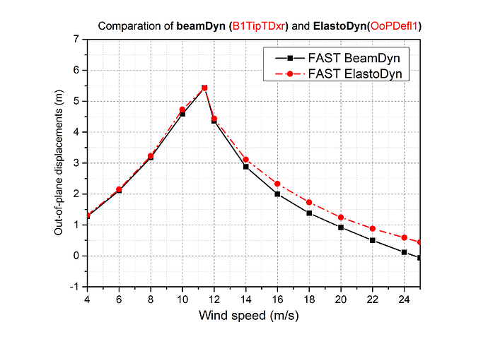
I find the BeamDyn results are very similar with ElastoDyn results for wind speeds below 11.4m/s, but the time-averaged In-plane deformations differ a lot for wind speeds above 11.4m/s, as shown below:
I know the modal approach for ElastoDyn is different with the geometrically exact beam model for BeamDyn, but I don not expect the In-plane deformations differ so much. So I have three questions:
(1) Does the IpDefl1 in ElastoDyn represents the same quantity with B1TipTDyr in BeamDyn?
(2) If so, why the large differences are only happen at above-rated wind speeds for In-Plane deformations?
(3) I noticed the B1TipTDyr is defined in the floating reference coordinate system fixed to the root of the moving beam, and is defined relative to the undeflected position. I know this floating coordinate system moves with hub motions and blade azimuth rotations, but I am not sure whether it rotate with blade pitch angles? as the blade pitch only introduces rigid body rotation.
please help me,
Best regards,
Lin Yang.
1 Like
Dear @Lin.Yang,
Actually, output IPDefl1 from ElastoDyn does not represent the same quantity as output B1TipTDyr in BeamDyn. IPDefl1 is in a coordinate system that is fixed in the hub (doesn’t pitch with the blade), but B1TipTDyr is in a coordinate system that is fixed in the root (does pitch with the blade). The more consistent comparison to B1TipTDyr in BeamDyn would be ElastoDyn output TipDyb1. Perhaps this explains the differences you are showing?
Best regards,
1 Like
Dear Jason,
Thanks for your reply and clarification! That is very helpful for me. Following your suggestions, I finally get reasonable results for the blade tip deformations as following:
As shown, the TipDyrb1 in ElastoDyn indeed agree well with the B1TipTDyr in BeamDyn. To obtain the Inp and Oop results in BeamDyn, I performed a coordinate transformation for the results of B1TipTDxr , B1TipTDyr with blade pitch angle. The results are donated as BeamDyn_Oop and BeamDyn_Inp, which are calculated as:
BeanDyn_Oop = B1TipTDxr * cos( pitch_angle ) + B1TipTDyr * sin( pitch_angle )
BeanDyn_Inp = - B1TipTDxr * sin( pitch_angle ) + B1TipTDyr * cos( pitch_angle )
the resutls show consistent trends with the Oop and Inp results from ElastoDyn while certain discrapancies exist for Inp. By using the 3-rd Wiener-Milenkovic parameter B1TipRDzr as an approximation to blade torsion, as shown below,
I find the negative torsional deformations (nose-down) may reasonably explain the decrease of Inp results in magnitude.
To bring this topic to a conclude, I have another three questions:
(1) Is the calculation process of BeamDyn_Inp and BeamDyn_Oop acceptable?
(2) Dose the term B1TipRDzr can be used as an approximation for blade torsion?
(3) If so, is the previous explanation for Inp discrepancy correct or not?
Best regards,
Lin Yang.
Dear @Lin.Yang,
I agree with your equation for BeamDyn_Oop and BeamDyn_Inp.
Regarding B1TipRDzr, see a similar discussion in the following forum topic: Extract blade tip torsional deformation from the Wiener-Milenković parameters in BeamDyn.
I agree that a small amount of blade torsion would influence in-plane deflection more than out-of-plane deflection.
Best regards,
1 Like
Dear Jason,
Thanks for your quick reply and confirmation. Now, I have a much clear understanding of the beamDyn and blade deformation features.
I hope this discussion would also be beneficial to other readers who are using beamDyn for blade aeroelasticity analysis or using beamDyn data for code validations.
Best regards,
Lin Yang.
3 Likes


