Standalone SubDyn Comparison with ANSYS

As part of a project thesis I am currently performing an analysis of a jacket tower structure of an onshore twin rotor wind turbine in both ANSYS Mechanical APDL and standalone SubDyn, to validate the suitability of either program for further research and design purposes.

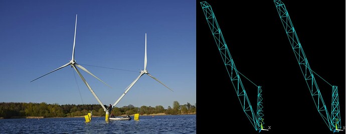
As I cannot provide the original data due to a confidentiality clause, I have provided a schematic overview of a similar turbine concept below (left). Please note that the turbine I am modelling is onshore with jacket structure and includes a base tower in between the two arms.
In addition I included the ANSYS structure models mentioned under 2) and 3), respectively.

After creating structure models in ANSYS and in SubDyn via the input file, I am currently facing the problem of having varying results and struggles validating them.
I have included the screenshots of my ANSYS model for better understanding.

  1. Currently the analysis is supposed to be static / steady-state with applied loads defined by displacements of the TP in SubDyn to obtain stiffness properties of the tower structure.

    Is it possible to perform the required, static type of analysis via standalone SubDyn?

  2. I have simplified the tower structure by only including one arm of the twin rotor, as SubDyn only allows for the definition of one TP. Please note that the TP is located at the upper left end of the arm structure.

    Initially I tried to implement the model with a symmetry axis (as I did in ANSYS), by including additional Base Reaction Joints with restrained OutOfSymmetryPlane DOFs in the Input File. However, the software was not able to retrieve results and there have been no hints in the ECHO or SUM files

    Does standalone SubDyn provide the option to create a symmetry axis in the model?

  3. As a result I modeled the tower structure and one arm. I have restrained all DOFs on the 4 Base Reaction Joints in SubDyn, but considering weight forces I feel that additional Boundary Conditions are required. SubDyn is running and providing results using the current model, but I am struggling to validate them.

    Are there general assumptions and/or Boundary Conditions to consider regarding the next steps?

Please let me know if I can provide additional information or data if required.
Please also let me know if there are general problems for modeling this kind of structure in SubDyn.

Thanks for your support and best regards
Nicolas
Dear @Nicolas.Kropff,

Here are my responses:

  1. Yes, the 6x6 stiffness matrix (Guyan stiffness matrix) of the 6-DOF TP with a clamped reaction is calculated and returned by SubDyn in its summary file.
  2. I’m not sure I fully understand how you tried to model the symmetry in SubDyn, but SubDyn does not support the ability to add a plane of symmetry to the model. I agree that at this time, SubDyn only supports a single 6-DOF TP (you can have multiple interface joints connected to the TP, but all of these joints will be connected rigidly).
  3. I’m not sure I fully understand what you asking. SubDyn supports a single 6-DOF TP interface, and as many reaction joints as you want, as long as full-system rigid-body modes are eliminated from the model (with the exception of no reaction joints, in which case the Guyan modes are the rigid-body modes, which we use when applying SubDyn to floating wind platforms).

Best regards,

Dear @Jason.Jonkman ,

thanks for your fast reply, it is much appreciated.

Please find my responses below:

  1. Noted, thank you!

  2. Noted, thank you!

  3. I was wondering if I need to define additional reactions joints with DOF constraints to my model, as the original twin rotor turbine includes two arms with turbines at their top. This would result in weight forces acting on the base tower from both sides, while my current model only includes one arm with resulting weight forces from just one side (imbalanced). My previous approach 2) of modeling a symmetry axis was a result of this model simplification, as discussed before.

    To be more specific: Can I compensate the imbalanced weight forces caused by my model simplification by defining additional reaction joints with locked DOFs?

  4. I have an additional question regarding the SubDyn Driver File. I originally tried to apply loads [N] to my TP by designating nAppliedLoads using the template Driver.dvr provided in the documentation. Unfortunately the approach has not worked so far, as the ECHO file also does not include my defined loads.

    Consequently I worked with steady displacement inputs (InputsMod=1) but have also struggled to validate the results.

Is it possible to apply loads via nAppliedLoads and/or are there obvious errors in the provided Driver-file?

Thanks four your support and best regards
Nicolas

Hi Nicolas,

I don’t see anything wrong in your input file. We have an example of driver with a prescribed force here:

(somehow it is not run in our r-test, and I forgot why). And it looks like yours. We probably didn’t include the echo of the load table, which is why you don’t see it in the echo file.

Regarding your point 3, I dont think there is an easy way to inforce a symmetry. I think the easiest approach would be to include a concentrated mass representing the rotor nacelle assembly. The best is to add a rigid link between the center of mass of the RNA and the top of your second tower. That should give the first order gravitational and inertial effects.

I hope that helps,

Emmanuel

Sorry I had to read the source code a couple of times as I got confused by the error handling, but steady and unsteady loads are supported by the driver. Please submit an issue on the OpenFAST github if they don’t seem to work.