Power and fatigue damage from FAST.Farm

Hi everyone,

I’m performing simulations on FAST.Farm in order to study fatigue damage in wind farms for my thesis.

In the following plots I’m changing wind direction (by changing the wind farm layout) and maintining all other variables of interest constant . I’m also using Turbsim to generate 24 wind fields (24 pairs of seeds) with 10 minutes of duration. I’m simulating a wind farm with 2 turbines based on the IEA-10.0-198-RWT reference wind turbine.

I have some questions about the plots:

1- For the power plot, shouldn’t the power from the downstream turbine (T2) become equal, at a certain wind direction, to the power from upstream turbine (T1) and remain constant and equal just like for T1? The difference in power between turbines is not too big (about 1%) but I still think they should overlap completely. Also, I find it weird that there is a peak in power for T2 at -15º. Could it be that I’m doing something wrong in the simulations, or that more seeds are needed?

2- For the fatigue plot at the tower base, I think that the damage in T2 shouldn’t be smaller than the damage in T1 (that is, should be equal or higher), instead it should have a minimum value equal to the damage in T1 . However, for some angles that isn’t true. Could adding more seeds solve the (potential) issue? Or is there any other reason that justifies the lower fatigue damage in T2?

Addtional info: wind speed=12m/s, turbulence intensity=12%, turbines aligned with wind (no yaw misalignment), distance between turbines equal to 8 diameters.

Any kind of advice is appreciated, thank you!

Best regards,

Dear @Raquel.Monteiro,

I agree with your intuition that the average power and fatigue of T2 should approach T1 for large wind directions. Can you provide more information about your simulation set up and averaging?

You mention that you are simulating 24 seeds of 10-minute simulations. Are you generating 10 minute periodic TurbSim data files and simulating FAST.Farm for longer than 10-minutes to ensure the start-up transient has passed before averaging?

Best regards,

Dear @Jason.Jonkman ,

For the simulations I’m using the files provided in IEA’s page in github with some alterations to fit my specific case. I’m using a TurbSim box with a spatial resolution of 10 m and a time step of 0.1 s . In case you want to check the files used in FAST.Farm:

------- InflowWind v3.01.* INPUT FILE -------------------------------------------------------------------------Generated with AeroElasticSE FAST driver

False                  Echo        - Echo input data to .ech (flag)3                      WindType    - switch for wind file type (1=steady; 2=uniform; 3=binary TurbSim FF; 4=binary Bladed-style FF; 5=HAWC format; 6=User defined; 7=native Bladed FF)0.0                    PropagationDir - Direction of wind propagation (meteorological rotation from aligned with X (positive rotates towards -Y) – degrees) (not used for native Bladed format WindType=7)0.0                    VFlowAng    - Upflow angle (degrees) (not used for native Bladed format WindType=7)False                  VelInterpCubic - Use cubic interpolation for velocity in time (false=linear, true=cubic) [Used with WindType=2,3,4,5,7]1                      NWindVel    - Number of points to output the wind velocity    (0 to 9)0.0                    WindVxiList - List of coordinates in the inertial X direction (m)0.0                    WindVyiList - List of coordinates in the inertial Y direction (m)119.0                  WindVziList - List of coordinates in the inertial Z direction (m)================== Parameters for Steady Wind Conditions [used only for WindType = 1] =========================5.0                    HWindSpeed  - Horizontal windspeed                            (m/s)119.0                  RefHt       - Reference height for horizontal wind speed      (m)0.2                    PLexp       - Power law exponent                              (-)================== Parameters for Uniform wind file   [used only for WindType = 2] ============================“none”                 Filename_Uni - Filename of time series data for uniform wind field.      (-)119.0                  RefHt_Uni   - Reference height for horizontal wind speed                (m)1.0                    RefLength   - Reference length for linear horizontal and vertical sheer (-)================== Parameters for Binary TurbSim Full-Field files   [used only for WindType = 3] ==============“90m_10mps.bts”        FileName_BTS - Name of the Full field wind file to use (.bts)================== Parameters for Binary Bladed-style Full-Field files   [used only for WindType = 4 or WindType = 7] =========“none”                 FilenameRoot - WindType=4: Rootname of the full-field wind file to use (.wnd, .sum); WindType=7: name of the intermediate file with wind scaling valuesFalse                  TowerFile   - Have tower file (.twr) (flag) ignored when WindType = 7================== Parameters for HAWC-format binary files  [Only used with WindType = 5] =====================“none”                 FileName_u  - name of the file containing the u-component fluctuating wind (.bin)“none”                 FileName_v  - name of the file containing the v-component fluctuating wind (.bin)“none”                 FileName_w  - name of the file containing the w-component fluctuating wind (.bin)2                      nx          - number of grids in the x direction (in the 3 files above) (-)2                      ny          - number of grids in the y direction (in the 3 files above) (-)2                      nz          - number of grids in the z direction (in the 3 files above) (-)10                     dx          - distance (in meters) between points in the x direction    (m)10                     dy          - distance (in meters) between points in the y direction    (m)10                     dz          - distance (in meters) between points in the z direction    (m)0.0                    RefHt_Hawc  - reference height; the height (in meters) of the vertical center of the grid (m)-------------   Scaling parameters for turbulence   ---------------------------------------------------------2                      ScaleMethod - Turbulence scaling method   [0 = none, 1 = direct scaling, 2 = calculate scaling factor based on a desired standard deviation]1.0                    SFx         - Turbulence scaling factor for the x direction (-)   [ScaleMethod=1]1.0                    SFy         - Turbulence scaling factor for the y direction (-)   [ScaleMethod=1]1.0                    SFz         - Turbulence scaling factor for the z direction (-)   [ScaleMethod=1]1.0                    SigmaFx     - Turbulence standard deviation to calculate scaling from in x direction (m/s)    [ScaleMethod=2]1.0                    SigmaFy     - Turbulence standard deviation to calculate scaling from in y direction (m/s)    [ScaleMethod=2]1.0                    SigmaFz     - Turbulence standard deviation to calculate scaling from in z direction (m/s)    [ScaleMethod=2]-------------   Mean wind profile parameters (added to HAWC-format files)   ---------------------------------12                    URef        - Mean u-component wind speed at the reference height (m/s)2                      WindProfile - Wind profile type (0=constant;1=logarithmic,2=power law)0.2                    PLExp_Hawc  - Power law exponent (-) (used for PL wind profile type only)0.03                    Z0          - Surface roughness length (m) (used for LG wind profile type only)0                      XOffset     - Initial offset in +x direction (shift of wind box) (-)================== LIDAR Parameters ===========================================================================0                      SensorType          - Switch for lidar configuration (0 = None, 1 = Single Point Beam(s), 2 = Continuous, 3 = Pulsed)0                      NumPulseGate        - Number of lidar measurement gates (used when SensorType = 3)30                     PulseSpacing        - Distance between range gates (m) (used when SensorType = 3)0                      NumBeam             - Number of lidar measurement beams (0-5)(used when SensorType = 1)-200                   FocalDistanceX      - Focal distance co-ordinates of the lidar beam in the x direction (relative to hub height) (only first coordinate used for SensorType 2 and 3) (m)0                      FocalDistanceY      - Focal distance co-ordinates of the lidar beam in the y direction (relative to hub height) (only first coordinate used for SensorType 2 and 3) (m)0                      FocalDistanceZ      - Focal distance co-ordinates of the lidar beam in the z direction (relative to hub height) (only first coordinate used for SensorType 2 and 3) (m)0.0 0.0 0.0            RotorApexOffsetPos  - Offset of the lidar from hub height (m)17                     URefLid             - Reference average wind speed for the lidar[m/s]0.25                   MeasurementInterval - Time between each measurement [s]False                  LidRadialVel        - TRUE => return radial component, FALSE => return ‘x’ direction estimate1                      ConsiderHubMotion   - Flag whether to consider the hub motion’s impact on Lidar measurements====================== OUTPUT ==================================================True                  SumPrint    - Print summary data to .IfW.sum (flag)OutList      - The next line(s) contains a list of output parameters.  See OutListParameters.xlsx for a listing of available output channels, (-)“Wind1VelX”               X-direction wind velocity at point WindList(1)“Wind1VelY”               Y-direction wind velocity at point WindList(1)“Wind1VelZ”               Z-direction wind velocity at point WindList(1)END of input file (the word “END” must appear in the first 3 columns of this last OutList line)

------- OpenFAST INPUT FILE -------------------------------------------
Generated with AeroElasticSE FAST driver
---------------------- SIMULATION CONTROL --------------------------------------
False                  Echo        - Echo input data to <RootName>.ech (flag)
"FATAL"                AbortLevel  - Error level when simulation should abort (string) {"WARNING", "SEVERE", "FATAL"}
1.0                    TMax        - Total run time (s)
0.0025                    DT          - Recommended module time step (s)
1                      InterpOrder - Interpolation order for input/output time history (-) {1=linear, 2=quadratic}
0                      NumCrctn    - Number of correction iterations (-) {0=explicit calculation, i.e., no corrections}
99999.0                DT_UJac     - Time between calls to get Jacobians (s)
1000000.0              UJacSclFact - Scaling factor used in Jacobians (-)
---------------------- FEATURE SWITCHES AND FLAGS ------------------------------
1                      CompElast   - Compute structural dynamics (switch) {1=ElastoDyn; 2=ElastoDyn + BeamDyn for blades; 3=Simplified ElastoDyn}
1                      CompInflow  - Compute inflow wind velocities (switch) {0=still air; 1=InflowWind; 2=external from ExtInflow}
2                      CompAero    - Compute aerodynamic loads (switch) {0=None; 1=AeroDisk; 2=AeroDyn; 3=ExtLoads}
1                      CompServo   - Compute control and electrical-drive dynamics (switch) {0=None; 1=ServoDyn}
0                      CompSeaSt   - Compute sea state information (switch) {0=None; 1=SeaState}
0                      CompHydro   - Compute hydrodynamic loads (switch) {0=None; 1=HydroDyn}
0                      CompSub     - Compute sub-structural dynamics (switch) {0=None; 1=SubDyn; 2=External Platform MCKF}
0                      CompMooring - Compute mooring system (switch) {0=None; 1=MAP++; 2=FEAMooring; 3=MoorDyn; 4=OrcaFlex}
0                      CompIce     - Compute ice loads (switch) {0=None; 1=IceFloe; 2=IceDyn}
0                      MHK         - MHK turbine type (switch) {0=Not an MHK turbine; 1=Fixed MHK turbine; 2=Floating MHK turbine}
---------------------- ENVIRONMENTAL CONDITIONS --------------------------------
9.80665                Gravity     - Gravitational acceleration (m/s^2)
1.225                  AirDens     - Air density (kg/m^3)
0                      WtrDens     - Water density (kg/m^3)
1.464e-05              KinVisc     - Kinematic viscosity of working fluid (m^2/s)
335                    SpdSound    - Speed of sound in working fluid (m/s)
103500                 Patm        - Atmospheric pressure (Pa) [used only for an MHK turbine cavitation check]
1700                   Pvap        - Vapour pressure of working fluid (Pa) [used only for an MHK turbine cavitation check]
000                    WtrDpth     - Water depth (m)
0                      MSL2SWL     - Offset between still-water level and mean sea level (m) [positive upward]
---------------------- INPUT FILES ---------------------------------------------
"IEA-10.0-198-RWT_ElastoDyn.dat" EDFile      - Name of file containing ElastoDyn input parameters (quoted string)
"unused"  BDBldFile(1) - Name of file containing BeamDyn input parameters for blade 1 (quoted string)
"unused"  BDBldFile(2) - Name of file containing BeamDyn input parameters for blade 2 (quoted string)
"unused"  BDBldFile(3) - Name of file containing BeamDyn input parameters for blade 3 (quoted string)
"IEA-10.0-198-RWT_InflowFile.dat" InflowFile  - Name of file containing inflow wind input parameters (quoted string)
"IEA-10.0-198-RWT_AeroDyn15.dat" AeroFile    - Name of file containing aerodynamic input parameters (quoted string)
"IEA-10.0-198-RWT_ServoDyn_WT1.dat" ServoFile   - Name of file containing control and electrical-drive input parameters (quoted string)
"IEA-10.0-198-RWT_SeaState.dat" SeaStFile   - Name of file containing sea state input parameters (quoted string)
"IEA-10.0-198-RWT_HydroDyn.dat" HydroFile   - Name of file containing hydrodynamic input parameters (quoted string)
"IEA-10.0-198-RWT_SubDyn.dat" SubFile     - Name of file containing sub-structural input parameters (quoted string)
"none"                 MooringFile - Name of file containing mooring system input parameters (quoted string)
"none"                 IceFile     - Name of file containing ice input parameters (quoted string)
---------------------- OUTPUT --------------------------------------------------
False                  SumPrint    - Print summary data to "<RootName>.sum" (flag)
10.0                   SttsTime    - Amount of time between screen status messages (s)
99999.0                ChkptTime   - Amount of time between creating checkpoint files for potential restart (s)
0.1                    DT_Out      - Time step for tabular output (s) (or "default")
20.0                    TStart      - Time to begin tabular output (s)
3                      OutFileFmt  - Format for tabular (time-marching) output file (switch) {1: text file [<RootName>.out], 2: binary file [<RootName>.outb], 3: both 1 and 2, 4: uncompressed binary [<RootName>.outb, 5: both 1 and 4}
True                   TabDelim    - Use tab delimiters in text tabular output file? (flag) {uses spaces if false}
"ES10.3E2"             OutFmt      - Format used for text tabular output, excluding the time channel.  Resulting field should be 10 characters. (quoted string)
---------------------- LINEARIZATION -------------------------------------------
False                  Linearize   - Linearization analysis (flag)
False                  CalcSteady  - Calculate a steady-state periodic operating point before linearization? [unused if Linearize=False] (flag)
3                      TrimCase    - Controller parameter to be trimmed {1:yaw; 2:torque; 3:pitch} [used only if CalcSteady=True] (-)
0.001                  TrimTol     - Tolerance for the rotational speed convergence [used only if CalcSteady=True] (-)
0.01                   TrimGain    - Proportional gain for the rotational speed error (>0) [used only if CalcSteady=True] (rad/(rad/s) for yaw or pitch; Nm/(rad/s) for torque)
0.0                    Twr_Kdmp    - Damping factor for the tower [used only if CalcSteady=True] (N/(m/s))
0.0                    Bld_Kdmp    - Damping factor for the blades [used only if CalcSteady=True] (N/(m/s))
2                      NLinTimes   - Number of times to linearize (-) [>=1] [unused if Linearize=False]
30.000000, 60.000000   LinTimes    - List of times at which to linearize (s) [1 to NLinTimes] [used only when Linearize=True and CalcSteady=False]
1                      LinInputs   - Inputs included in linearization (switch) {0=none; 1=standard; 2=all module inputs (debug)} [unused if Linearize=False]
1                      LinOutputs  - Outputs included in linearization (switch) {0=none; 1=from OutList(s); 2=all module outputs (debug)} [unused if Linearize=False]
False                  LinOutJac   - Include full Jacobians in linearization output (for debug) (flag) [unused if Linearize=False; used only if LinInputs=LinOutputs=2]
False                  LinOutMod   - Write module-level linearization output files in addition to output for full system? (flag) [unused if Linearize=False]
---------------------- VISUALIZATION ------------------------------------------
0                      WrVTK       - VTK visualization data output: (switch) {0=none; 1=initialization data only; 2=animation}
1                      VTK_type    - Type of VTK visualization data: (switch) {1=surfaces; 2=basic meshes (lines/points); 3=all meshes (debug)} [unused if WrVTK=0]
False                  VTK_fields  - Write mesh fields to VTK data files? (flag) {true/false} [unused if WrVTK=0]
10.0                   VTK_fps     - Frame rate for VTK output (frames per second){will use closest integer multiple of DT} [used only if WrVTK=2]

------- FAST.Farm for OpenFAST INPUT FILE -------------------------------------------------
FAST.Farm input file, using two turbines separated by 3D downstream and an offset of 30m, with a turbulent inflow given by one turbsim box
--- SIMULATION CONTROL ---
False              Echo               - Echo input data to <RootName>.ech? (flag)
FATAL              AbortLevel         - Error level when simulation should abort (string) {"WARNING", "SEVERE", "FATAL"}
700              TMax               - Total run time (s) [>=0.0]
False              UseSC              - Use a super controller? (flag)
2                  Mod_AmbWind        - Ambient wind model (-) (switch) {1: high-fidelity precursor in VTK format, 2: one InflowWind module, 3: multiple instances of InflowWind module}
2                  Mod_WaveField      - Wave field handling (-) (switch) {1: use individual HydroDyn inputs without adjustment, 2: adjust wave phases based on turbine offsets from farm origin}
0                  Mod_SharedMooring  - Shared mooring system model (switch) {0: None, 3=MoorDyn}}
--- SUPER CONTROLLER --- [used only for UseSC=True]
"unused"           SC_FileName        - Name/location of the dynamic library {.dll [Windows] or .so [Linux]} containing the Super Controller algorithms (quoated string)
--- SHARED MOORING SYSTEM --- [used only for Mod_SharedMoor>0]
""                 SharedMoorFile     - Name of file containing shared mooring system input parameters (quoted string) [used only when Mod_SharedMooring > 0]
0.04	           DT_Mooring         - Time step for farm-level mooring coupling with each turbine (s) [used only when Mod_SharedMooring > 0]
true              WrMooringVis       - Write shared mooring visualization, at the global FAST.Farm time step (-) [only used for Mod_SharedMooring=3]
--- AMBIENT WIND: PRECURSOR IN VTK FORMAT --- [used only for Mod_AmbWind=1]
3.0                DT_Low-VTK         - Time step for low -resolution wind data input files; will be used as the global FAST.Farm time step (s) [>0.0]
0.1                DT_High-VTK        - Time step for high-resolution wind data input files (s) [>0.0]
"unused"           WindFilePath       - Path name to VTK wind data files from precursor (string)
False              ChkWndFiles        - Check all the ambient wind files for data consistency? (flag)
--- AMBIENT WIND: INFLOWWIND MODULE --- [used only for Mod_AmbWind=2 or 3]
3.0                DT_Low             - Time step for low -resolution wind data interpolation; will be used as the global FAST.Farm time step (s) [>0.0]
0.1                DT_High            - Time step for high-resolution wind data interpolation (s) [>0.0]
223                NX_Low             - Number  of low -resolution spatial nodes in X direction for wind data interpolation (-) [>=2]
141                 NY_Low             - Number  of low -resolution spatial nodes in Y direction for wind data interpolation (-) [>=2]
23                 NZ_Low             - Number  of low -resolution spatial nodes in Z direction for wind data interpolation (-) [>=2]
-250               X0_Low             - Origin  of low -resolution spatial nodes in X direction for wind data interpolation (m)
-700.0             Y0_Low             - Origin  of low -resolution spatial nodes in Y direction for wind data interpolation (m)
5.0                Z0_Low             - Origin  of low -resolution spatial nodes in Z direction for wind data interpolation (m)
10.17              dX_Low             - Spacing of low -resolution spatial nodes in X direction for wind data interpolation (m) [>0.0]
10.0               dY_Low             - Spacing of low -resolution spatial nodes in Y direction for wind data interpolation (m) [>0.0]
10                 dZ_Low             - Spacing of low -resolution spatial nodes in Z direction for wind data interpolation (m) [>0.0]
46                NX_High            - Number  of high-resolution spatial nodes in X direction for wind data interpolation (-) [>=2]
25                 NY_High            - Number  of high-resolution spatial nodes in Y direction for wind data interpolation (-) [>=2]
24                 NZ_High            - Number  of high-resolution spatial nodes in Z direction for wind data interpolation (-) [>=2]
"IEA-10.0-198-RWT_InflowFile.dat"           InflowFile         - Name of file containing InflowWind module input parameters (quoted string)
--- WIND TURBINES ---
2                  NumTurbines        - Number of wind turbines (-) [>=1]                         [last 6 columns below used only for Mod_AmbWind=2 or 3]
WT_X    WT_Y   WT_Z   WT_FASTInFile             X0_High  Y0_High  Z0_High  dX_High  dY_High  dZ_High
(m)     (m)    (m)    (string)          (m)      (m)      (m)      (m)      (m)      (m)
0 0 0 "IEA-10.0-198-RWT1.fst" -100.49 -120.0 5.0 10.17 10.0 10.0
1578 138.1 0 "IEA-10.0-198-RWT2.fst" 1478 18.1 5.0 10.17 10.0 10.0
--- WAKE DYNAMICS ---
1                  Mod_Wake           - Switch between wake formulations {1:Polar, 2:Curl, 3:Cartesian} (-) (switch)
198                RotorDiamRef       - Reference turbine rotor diameter for wake calculations (m) [>0.0]
2                  dr                 - Radial increment of radial finite-difference grid (m) [>0.0]
125                 NumRadii           - Number of radii in the radial finite-difference grid (-) [>=2]
156                NumPlanes          - Number of wake planes (-) [>=2]
0.17               f_c                - Cutoff (corner) frequency of the low-pass time-filter for the wake advection, deflection, and meandering model [recommended=1.28*U0/R] (Hz) [>0.0] or DEFAULT [DEFAULT=12.5/R, R estimated from dr and NumRadii, not recommended]
DEFAULT            C_HWkDfl_O         - Calibrated parameter in the correction for wake deflection defining the horizontal offset at the rotor                                               (m    ) or DEFAULT [DEFAULT= 0.0  ]
DEFAULT            C_HWkDfl_OY        - Calibrated parameter in the correction for wake deflection defining the horizontal offset at the rotor scaled with                         yaw error (m/deg) or DEFAULT [DEFAULT= 0.0 if Mod_Wake is 2, 0.3 otherwise]
DEFAULT            C_HWkDfl_x         - Calibrated parameter in the correction for wake deflection defining the horizontal offset              scaled with downstream distance               (-    ) or DEFAULT [DEFAULT= 0.0  ]
DEFAULT            C_HWkDfl_xY        - Calibrated parameter in the correction for wake deflection defining the horizontal offset              scaled with downstream distance and yaw error (1/deg) or DEFAULT [DEFAULT= 0.0 if Mod_Wake is 2, -0.004 otherwise]
1.8               C_NearWake         - Calibrated parameter for the near-wake correction (-) [>1.0 and <2.5] or DEFAULT [DEFAULT=1.8]
DEFAULT       k_vAmb        - Calibrated parameters for the influence of the ambient turbulence in the eddy viscosity (set of 5 parameters: k, FMin, DMin, DMax, Exp) (-) [>=0.0, >=0.0 and <=1.0, >=0.0, >DMin, >=0.0] or DEFAULT [DEFAULT=0.05, 1.0, 0.0, 1.0, 0.01]
DEFAULT       k_vShr        - Calibrated parameters for the influence of the shear layer in the eddy viscosity (set of 5 parameters: k, FMin, DMin, DMax, Exp) (-) [>=0.0, >=0.0 and <=1.0, >=0.0, >DMin, >=0.0] or DEFAULT [DEFAULT=0.016, 0.2, 3.0, 25.0, 0.1]
DEFAULT            Mod_WakeDiam       - Wake diameter calculation model (-) (switch) {1: rotor diameter, 2: velocity based, 3: mass-flux based, 4: momentum-flux based} or DEFAULT [DEFAULT=1]
DEFAULT            C_WakeDiam         - Calibrated parameter for wake diameter calculation (-) [>0.0 and <0.99] or DEFAULT [DEFAULT=0.95] [unused for Mod_WakeDiam=1]
DEFAULT            Mod_Meander        - Spatial filter model for wake meandering (-) (switch) {1: uniform, 2: truncated jinc, 3: windowed jinc} or DEFAULT [DEFAULT=3]
DEFAULT            C_Meander          - Calibrated parameter for wake meandering (-) [>=1.0] or DEFAULT [DEFAULT=1.9]
--- CURLED-WAKE PARAMETERS [only used if Mod_Wake=2 or 3] ---
DEFAULT            Swirl              - Switch to include swirl velocities in wake (-) (switch) [DEFAULT=TRUE]
DEFAULT            k_VortexDecay      - Vortex decay constant for curl (-) [DEFAULT=0.0001]
DEFAULT            NumVortices        - The number of vortices in the curled wake model (-) [DEFAULT=100]
DEFAULT            sigma_D            - The width of the vortices in the curled wake model non-dimesionalized by rotor diameter (-) [DEFAULT=0.2]
DEFAULT            FilterInit         - Switch to filter the initial wake plane deficit and select the number of grid points for the filter {0: no filter, 1: filter of size 1} or DEFAULT [DEFAULT=1] [unused for Mod_Wake=1] (switch)
DEFAULT            k_vCurl            - Calibrated parameter for scaling the eddy viscosity in the curled-wake model (-) [>=0] or DEFAULT [DEFAULT=2.0 ]
DEFAULT            Mod_Projection     - Switch to select how the wake plane velocity is projected in AWAE {1: keep all components, 2: project against plane normal} or DEFAULT [DEFAULT=1: if Mod_Wake is 1 or 3, or DEFAULT=2: if Mod_Wake is 2] (switch)
--- WAKE-ADDED TURBULENCE ---
2                  WAT                - Switch between wake-added turbulence box options {0: no wake added turbulence, 1: predefined turbulence box, 2: user defined turbulence box} (switch)
"C:\\Users\\raque\\.spyder-py3\\ex_t\\FFarm_template\\FFDB_D100_512x512x64.u" WAT_BoxFile  - Filepath to the file containing the u-component of the turbulence box (either predefined or user-defined) (quoted string)
512, 512, 64       WAT_NxNyNz         - Number of points in the x, y, and z directions of the WAT_BoxFile [used only if WAT=2, derived value if WAT=1] (-)
5.0, 5.0, 5.0      WAT_DxDyDz         - Distance (in meters) between points in the x, y, and z directions of the WAT_BoxFile [used only if WAT=2, derived value if WAT=1] (m)
default            WAT_ScaleBox       - Flag to scale the input turbulence box to zero mean and unit standard deviation at every node [DEFAULT=False] (flag)
default            WAT_k_Def          - Calibrated parameters for the influence of the maximum wake deficit on wake-added turbulence (set of 5 parameters: k_Def, FMin, DMin, DMax, Exp) (-) [>=0.0, >=0.0 and <=1.0, >=0.0, >DMin, >=0.0] or DEFAULT [DEFAULT=[0.6, 0.0, 0.0, 2.0, 1.0 ]]
default            WAT_k_Grad         - Calibrated parameters for the influence of the radial velocity gradient of the wake deficit on wake-added turbulence (set of 5 parameters: k_Grad, FMin, DMin, DMax, Exp) (-) [>=0.0, >=0.0 and <=1.0, >=0.0, >DMin, >=0.0] or DEFAULT [DEFAULT=[3.0, 0.0, 0.0, 12.0, 0.65]
--- VISUALIZATION ---
False              WrDisWind          - Write low- and high-resolution disturbed wind data to <RootName>.Low.Dis.t<n>.vtk etc.? (flag)
0    NOutDisWindXY      - Number of XY planes for output of disturbed wind data across the low-resolution domain to <RootName>.Low.DisXY<n_out>.t<n>.vtk (-) [0 to 99]
90.0               OutDisWindZ        - Z coordinates of XY planes for output of disturbed wind data across the low-resolution domain (m) [1 to NOutDisWindXY] [unused for NOutDisWindXY=0]
0                  NOutDisWindYZ      - Number of YZ planes for output of disturbed wind data across the low-resolution domain to <RootName>/Low.DisYZ<n_out>.t<n>.vtk (-) [0 to 999]
63.,441.           OutDisWindX        - X coordinates of YZ planes for output of disturbed wind data across the low-resolution domain (m) [1 to NOutDisWindYZ] [unused for NOutDisWindYZ=0]
0                  NOutDisWindXZ      - Number of XZ planes for output of disturbed wind data across the low-resolution domain to <RootName>/Low.DisXZ<n_out>.t<n>.vtk (-) [0 to 999]
0.0                OutDisWindY        - Y coordinates of XZ planes for output of disturbed wind data across the low-resolution domain (m) [1 to NOutDisWindXZ] [unused for NOutDisWindXZ=0]
3.0                WrDisDT            - Time step for disturbed wind visualization output (s) [>0.0] or DEFAULT [DEFAULT=DT_Low or DT_Low-VTK] [unused for WrDisWind=False and NOutDisWindXY=NOutDisWindYZ=NOutDisWindXZ=0]
--- OUTPUT ---
False              SumPrint           - Print summary data to <RootName>.sum? (flag)
99999.9            ChkptTime          - Amount of time between creating checkpoint files for potential restart (s) [>0.0]
0.0                TStart             - Time to begin tabular output (s) [>=0.0]
1                  OutFileFmt         - Format for tabular (time-marching) output file (switch) {1: text file [<RootName>.out], 2: binary file [<RootName>.outb], 3: both}
True               TabDelim           - Use tab delimiters in text tabular output file? (flag) {uses spaces if False}
"ES10.3E2"         OutFmt             - Format used for text tabular output, excluding the time channel.  Resulting field should be 10 characters. (quoted string)
DEFAULT            OutAllPlanes       - Output all wake planes at all time steps. [DEFAULT=False]
7                  NOutRadii          - Number of radial nodes         for wake output for an individual rotor (-) [0 to 20]
0, 2, 5, 11, 17, 21, 39  OutRadii     - List of radial nodes         for wake output for an individual rotor (-) [1 to NOutRadii] [unused for NOutRadii=0]
1                  NOutDist           - Number of downstream distances for wake output for an individual rotor (-) [0 to 9 ]
63.0               OutDist            - List of downstream distances for wake output for an individual rotor (m) [1 to NOutDist ] [unused for NOutDist =0]
0                  NWindVel           - Number of points for wind output (-) [0 to 9]
0.0                WindVelX           - List of coordinates in the X direction for wind output (m) [1 to NWindVel] [unused for NWindVel=0]
0.0                WindVelY           - List of coordinates in the Y direction for wind output (m) [1 to NWindVel] [unused for NWindVel=0]
90.0               WindVelZ           - List of coordinates in the Z direction for wind output (m) [1 to NWindVel] [unused for NWindVel=0]
                   OutList            - The next line(s) contains a list of output parameters.  See OutListParameters.xlsx for a listing of available output channels (quoted string)
"RtVAmbT1"
"RtVAmbT2"
"RtVRelT2"
"YawErrT1"
"YawErrT2"
"CtT1N02      , CtT1N03      , CtT1N04      , CtT1N05      , CtT1N06"
WkAxsXT2D1" 
WkAxsYT2D1" 
WkAxsZT2D1" 
WkPosXT2D1" 
WkPosYT2D1" 
WkPosZT2D1" 
"WkDfVxT1N01D1, WkDfVxT1N02D1, WkDfVxT1N03D1, WkDfVxT1N04D1, WkDfVxT1N05D1, WkDfVxT1N06D1, WkDfVxT1N07D1"
"WkDfVrT1N01D1, WkDfVrT1N02D1, WkDfVrT1N03D1, WkDfVrT1N04D1, WkDfVrT1N05D1, WkDfVrT1N06D1, WkDfVrT1N07D1"
"WkDfVxT2N01D1, WkDfVxT2N02D1, WkDfVxT2N03D1, WkDfVxT2N04D1, WkDfVxT2N05D1, WkDfVxT2N06D1, WkDfVxT2N07D1"
"WkDfVrT2N01D1, WkDfVrT2N02D1, WkDfVrT2N03D1, WkDfVrT2N04D1, WkDfVrT2N05D1, WkDfVrT2N06D1, WkDfVrT2N07D1"
END of input file (the word "END" must appear in the first 3 columns of this last OutList line)

I’ve put here only one ServoDyn and one OpenFAST since they are the same for the second wind turbine.

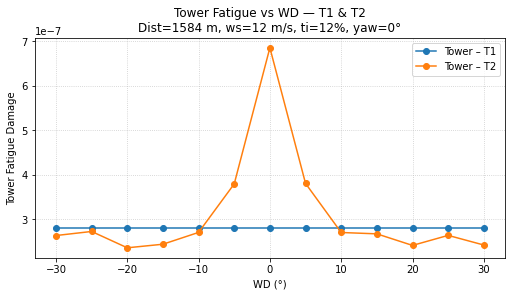
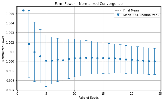
I’m simulating for more than 10 minutes so that I can cut off the transient and only averaging after that. For both power and fatigue the average is over time and seeds. The plot of tower fatigue in my first post refers to the maximum fatigue damage at the tower base due to fore-aft and side-to-side bending moments .

If you need any more information please let me know.

Best regards,

Since I didn’t have enough space in the previous post, the rest of the files :

------- AERODYN v15.03.* INPUT FILE ------------------------------------------------
Generated with AeroElasticSE FAST driver
======  General Options  ============================================================================
False                  Echo        - Echo the input to "<rootname>.AD.ech"?  (flag)
Default                DTAero      - Time interval for aerodynamic calculations {or "default"} (s)
1                      Wake_Mod    - Wake/induction model (switch) {0=none, 1=BEMT, 3=OLAF} [Wake_Mod cannot be 2 or 3 when linearizing]
0                      TwrPotent   - Type tower influence on wind based on potential flow around the tower (switch) {0=none, 1=baseline potential flow, 2=potential flow with Bak correction}
0                      TwrShadow   - Calculate tower influence on wind based on downstream tower shadow (switch) {0=none, 1=Powles model, 2=Eames model}
False                   TwrAero     - Calculate tower aerodynamic loads? (flag)
False                  CavitCheck  - Perform cavitation check? (flag) [UA_Mod must be 0 when CavitCheck=true]
False                  Buoyancy    - Include buoyancy effects? (flag)
False                  NacelleDrag - Include Nacelle Drag effects? (flag)
False                  CompAA      - Flag to compute AeroAcoustics calculation [used only when Wake_Mod = 1 or 2]
AeroAcousticsInput.dat AA_InputFile - AeroAcoustics input file [used only when CompAA=true]
======  Environmental Conditions  ===================================================================
1.225                  AirDens     - Air density (kg/m^3)
1.4775510204081632e-05 KinVisc     - Kinematic viscosity of working fluid (m^2/s)
340.0                  SpdSound    - Speed of sound in working fluid (m/s)
103500.0               Patm        - Atmospheric pressure (Pa) [used only when CavitCheck=True]
1700.0                 Pvap        - Vapour pressure of working fluid (Pa) [used only when CavitCheck=True]
======  Blade-Element/Momentum Theory Options  ====================================================== [unused when Wake_Mod=0 or 3, except for BEM_Mod]
1                      BEM_Mod     - BEM model {1=legacy NoSweepPitchTwist, 2=polar} (switch) [used for all Wake_Mod to determine output coordinate system]
--- Skew correction
1                      Skew_Mod    - Skew model {0=No skew model, -1=Remove non-normal component for linearization, 1=skew model active}
False                  SkewMomCorr - Turn the skew momentum correction on or off [used only when Skew_Mod=1]
1                      SkewRedistr_Mod - Type of skewed-wake correction model (switch) {0=no redistribution, 1=Glauert/Pitt/Peters, default=1} [used only when Skew_Mod=1]
1.4726215563702154     SkewRedistrFactor - Constant used in Pitt/Peters skewed wake model {or "default" is 15/32*pi} (-) [used only when Skew_Mod=1 and SkewRedistr_Mod=1]
--- BEM algorithm 
True                   TipLoss     - Use the Prandtl tip-loss model? (flag) [unused when Wake_Mod=0 or 3]
True                   HubLoss     - Use the Prandtl hub-loss model? (flag) [unused when Wake_Mod=0 or 3]
True                   TanInd      - Include tangential induction in BEMT calculations? (flag) [unused when Wake_Mod=0 or 3]
False                  AIDrag      - Include the drag term in the axial-induction calculation? (flag) [unused when Wake_Mod=0 or 3]
False                  TIDrag      - Include the drag term in the tangential-induction calculation? (flag) [unused when Wake_Mod=0,3 or TanInd=FALSE]
"Default"              IndToler    - Convergence tolerance for BEMT nonlinear solve residual equation {or "default"} (-) [unused when Wake_Mod=0 or 3]
100                    MaxIter     - Maximum number of iteration steps (-) [unused when Wake_Mod=0]
--- Shear correction
False                  SectAvg     - Use sector averaging (flag)
1                      SectAvgWeighting - Weighting function for sector average {1=Uniform, default=1} within a sector centered on the blade (switch) [used only when SectAvg=True]
default                SectAvgNPoints - Number of points per sectors (-) {default=5} [used only when SectAvg=True]
default                SectAvgPsiBwd - Backward azimuth relative to blade where the sector starts (<=0) {default=-60} (deg) [used only when SectAvg=True]
default                SectAvgPsiFwd - Forward azimuth relative to blade where the sector ends (>=0) {default=60} (deg) [used only when SectAvg=True]
--- Dynamic wake/inflow
0                      DBEMT_Mod   - Type of dynamic BEMT (DBEMT) model {0=No Dynamic Wake, -1=Frozen Wake for linearization, 1:constant tau1, 2=time-dependent tau1, 3=constant tau1 with continuous formulation} (-)
23.7972                tau1_const  - Time constant for DBEMT (s) [used only when Wake_Mod=2 and DBEMT_Mod=1]
======  OLAF -- cOnvecting LAgrangian Filaments (Free Vortex Wake) Theory Options  ================== [used only when Wake_Mod=3]
IEA-10.0-198-RWT_OLAF.dat OLAFInputFileName - Input file for OLAF [used only when Wake_Mod=3]
======  Unsteady Airfoil Aerodynamics Options  ====================================================
True                   AoA34       - Sample the angle of attack (AoA) at the 3/4 chord or the AC point {default=True} [always used]
0                      UA_Mod      - Unsteady Aero Model Switch (switch) {0=Quasi-steady (no UA), 2=B-L Gonzalez, 3=B-L Minnema/Pierce, 4=B-L HGM 4-states, 5=B-L HGM+vortex 5 states, 6=Oye, 7=Boeing-Vertol}
True                   FLookup     - Flag to indicate whether a lookup for f' will be calculated (TRUE) or whether best-fit exponential equations will be used (FALSE); if FALSE S1-S4 must be provided in airfoil input files (flag) [used only when UA_Mod>0]
3               IntegrationMethod  - Switch to indicate which integration method UA uses (1=RK4, 2=AB4, 3=ABM4, 4=BDF2)
0                      UAStartRad  - Starting radius for dynamic stall (fraction of rotor radius [0.0,1.0]) [used only when UA_Mod>0; if line is missing UAStartRad=0]
1                      UAEndRad    - Ending radius for dynamic stall (fraction of rotor radius [0.0,1.0]) [used only when UA_Mod>0; if line is missing UAEndRad=1]
======  Airfoil Information =========================================================================
1                      AFTabMod    - Interpolation method for multiple airfoil tables {1=1D interpolation on AoA (first table only); 2=2D interpolation on AoA and Re; 3=2D interpolation on AoA and UserProp} (-)
1                      InCol_Alfa  - The column in the airfoil tables that contains the angle of attack (-)
2                      InCol_Cl    - The column in the airfoil tables that contains the lift coefficient (-)
3                      InCol_Cd    - The column in the airfoil tables that contains the drag coefficient (-)
4                      InCol_Cm    - The column in the airfoil tables that contains the pitching-moment coefficient; use zero if there is no Cm column (-)
0                      InCol_Cpmin - The column in the airfoil tables that contains the Cpmin coefficient; use zero if there is no Cpmin column (-)
30                     NumAFfiles  - Number of airfoil files used (-)
"../../Airfoils/IEA-10.0-198-RWT_AeroDyn15_Polar_00.dat"    AFNames            - Airfoil file names (NumAFfiles lines) (quoted strings)
"../../Airfoils/IEA-10.0-198-RWT_AeroDyn15_Polar_01.dat"
"../../Airfoils/IEA-10.0-198-RWT_AeroDyn15_Polar_02.dat"
"../../Airfoils/IEA-10.0-198-RWT_AeroDyn15_Polar_03.dat"
"../../Airfoils/IEA-10.0-198-RWT_AeroDyn15_Polar_04.dat"
"../../Airfoils/IEA-10.0-198-RWT_AeroDyn15_Polar_05.dat"
"../../Airfoils/IEA-10.0-198-RWT_AeroDyn15_Polar_06.dat"
"../../Airfoils/IEA-10.0-198-RWT_AeroDyn15_Polar_07.dat"
"../../Airfoils/IEA-10.0-198-RWT_AeroDyn15_Polar_08.dat"
"../../Airfoils/IEA-10.0-198-RWT_AeroDyn15_Polar_09.dat"
"../../Airfoils/IEA-10.0-198-RWT_AeroDyn15_Polar_10.dat"
"../../Airfoils/IEA-10.0-198-RWT_AeroDyn15_Polar_11.dat"
"../../Airfoils/IEA-10.0-198-RWT_AeroDyn15_Polar_12.dat"
"../../Airfoils/IEA-10.0-198-RWT_AeroDyn15_Polar_13.dat"
"../../Airfoils/IEA-10.0-198-RWT_AeroDyn15_Polar_14.dat"
"../../Airfoils/IEA-10.0-198-RWT_AeroDyn15_Polar_15.dat"
"../../Airfoils/IEA-10.0-198-RWT_AeroDyn15_Polar_16.dat"
"../../Airfoils/IEA-10.0-198-RWT_AeroDyn15_Polar_17.dat"
"../../Airfoils/IEA-10.0-198-RWT_AeroDyn15_Polar_18.dat"
"../../Airfoils/IEA-10.0-198-RWT_AeroDyn15_Polar_19.dat"
"../../Airfoils/IEA-10.0-198-RWT_AeroDyn15_Polar_20.dat"
"../../Airfoils/IEA-10.0-198-RWT_AeroDyn15_Polar_21.dat"
"../../Airfoils/IEA-10.0-198-RWT_AeroDyn15_Polar_22.dat"
"../../Airfoils/IEA-10.0-198-RWT_AeroDyn15_Polar_23.dat"
"../../Airfoils/IEA-10.0-198-RWT_AeroDyn15_Polar_24.dat"
"../../Airfoils/IEA-10.0-198-RWT_AeroDyn15_Polar_25.dat"
"../../Airfoils/IEA-10.0-198-RWT_AeroDyn15_Polar_26.dat"
"../../Airfoils/IEA-10.0-198-RWT_AeroDyn15_Polar_27.dat"
"../../Airfoils/IEA-10.0-198-RWT_AeroDyn15_Polar_28.dat"
"../../Airfoils/IEA-10.0-198-RWT_AeroDyn15_Polar_29.dat"
======  Rotor/Blade Properties  =====================================================================
True                   UseBlCm     - Include aerodynamic pitching moment in calculations?  (flag)
"IEA-10.0-198-RWT_AeroDyn15_blade.dat" ADBlFile(1) - Name of file containing distributed aerodynamic properties for Blade #1 (-)
"IEA-10.0-198-RWT_AeroDyn15_blade.dat" ADBlFile(2) - Name of file containing distributed aerodynamic properties for Blade #2 (-) [unused if NumBl < 2]
"IEA-10.0-198-RWT_AeroDyn15_blade.dat" ADBlFile(3) - Name of file containing distributed aerodynamic properties for Blade #3 (-) [unused if NumBl < 3]
======  Hub Properties ============================================================================== [used only when Buoyancy=True]
0                      VolHub      - Hub volume (m^3)
0                      HubCenBx    - Hub center of buoyancy x direction offset (m)
======  Nacelle Properties ========================================================================== [used only when Buoyancy=True or NacelleDrag=True]
0                      VolNac      - Nacelle volume (m^3)
0.0, 0.0, 0.0   NacCenB            - Position of nacelle center of buoyancy from yaw bearing in nacelle coordinates (m)
0, 0, 0      NacArea        - Projected area of the nacelle in X, Y, Z in the nacelle coordinate system (m^2)
0, 0, 0   NacCd          - Drag coefficient for the nacelle areas defined above (-)
0, 0, 0         NacDragAC          - Position of aerodynamic center of nacelle drag in nacelle coordinates (m)
======  Tail Fin Aerodynamics =======================================================================
False                  TFinAero    - Calculate tail fin aerodynamics model (flag)
"unused"               TFinFile    - Input file for tail fin aerodynamics [used only when TFinAero=True]
======  Tower Influence and Aerodynamics ============================================================ [used only when TwrPotent/=0, TwrShadow/=0, TwrAero=True, or Buoyancy=True]
11                     NumTwrNds   - Number of tower nodes used in the analysis  (-) [used only when TwrPotent/=0, TwrShadow/=0, TwrAero=True, or Buoyancy=True]
TwrElev        TwrDiam        TwrCd          TwrTI          TwrCb !TwrTI used only with TwrShadow=2, TwrCb used only with Buoyancy=True
(m)              (m)           (-)            (-)            (-)
 1.000000000000000e+01  8.300000000000001e+00  5.000000000000000e-01  1.000000000000000e-01  0.000000000000000e+00 
 2.051000000000000e+01  8.020000000000000e+00  5.000000000000000e-01  1.000000000000000e-01  0.000000000000000e+00 
 3.101000000000000e+01  7.740000000000000e+00  5.000000000000000e-01  1.000000000000000e-01  0.000000000000000e+00 
 4.152000000000000e+01  7.460000000000000e+00  5.000000000000000e-01  1.000000000000000e-01  0.000000000000000e+00 
 5.202000000000000e+01  7.190000000000000e+00  5.000000000000000e-01  1.000000000000000e-01  0.000000000000000e+00 
 6.252999999999999e+01  6.910000000000000e+00  5.000000000000000e-01  1.000000000000000e-01  0.000000000000000e+00 
 7.303000000000000e+01  6.630000000000000e+00  5.000000000000000e-01  1.000000000000000e-01  0.000000000000000e+00 
 8.354000000000001e+01  6.350000000000000e+00  5.000000000000000e-01  1.000000000000000e-01  0.000000000000000e+00 
 9.404000000000001e+01  6.070000000000000e+00  5.000000000000000e-01  1.000000000000000e-01  0.000000000000000e+00 
 1.045500000000000e+02  5.790000000000000e+00  5.000000000000000e-01  1.000000000000000e-01  0.000000000000000e+00 
 1.156300000000000e+02  5.500000000000000e+00  5.000000000000000e-01  1.000000000000000e-01  0.000000000000000e+00 
======  Outputs  ====================================================================================
False                  SumPrint    - Generate a summary file listing input options and interpolated properties to "<rootname>.AD.sum"?  (flag)
9                      NBlOuts     - Number of blade node outputs [0 - 9] (-)
4, 7, 10, 13, 15, 18, 21, 24, 27 BlOutNd     - Blade nodes whose values will be output  (-)
0                      NTwOuts     - Number of tower node outputs [0 - 9]  (-)
0                      TwOutNd     - Tower nodes whose values will be output  (-)
                   OutList             - The next line(s) contains a list of output parameters.  See OutListParameters.xlsx for a listing of available output channels, (-)
"RtTSR"
END of input file (the word "END" must appear in the first 3 columns of this last OutList line)
---------------------- NODE OUTPUTS --------------------------------------------
0                      BldNd_BladesOut  - Number of blades to output all node information at.  Up to number of blades on turbine. (-)
ALL                    BldNd_BlOutNd   - Specify a portion of the nodes to output. {"ALL", "Tip", "Root", or a list of node numbers} (-)
                       OutList_Nodal - The next line(s) contains a list of output parameters.  See OutListParameters.xlsx for a listing of available output channels, (-)

END (the word "END" must appear in the first 3 columns of this last OutList line in the optional nodal output section)
====================================================================================================
------- ELASTODYN v1.03.* INPUT FILE -------------------------------------------
Generated with AeroElasticSE FAST driver
---------------------- SIMULATION CONTROL --------------------------------------
False                  Echo        - Echo input data to "<RootName>.ech" (flag)
3                      Method      - Integration method: {1: RK4, 2: AB4, or 3: ABM4} (-)
Default                DT          - Integration time step (s)
---------------------- DEGREES OF FREEDOM --------------------------------------
True                   FlapDOF1    - First flapwise blade mode DOF (flag)
True                   FlapDOF2    - Second flapwise blade mode DOF (flag)
True                   EdgeDOF     - First edgewise blade mode DOF (flag)
False                  TeetDOF     - Rotor-teeter DOF (flag) [unused for 3 blades]
True                  DrTrDOF     - Drivetrain rotational-flexibility DOF (flag)
True                   GenDOF      - Generator DOF (flag)
True                   YawDOF      - Yaw DOF (flag)
True                   TwFADOF1    - First fore-aft tower bending-mode DOF (flag)
True                    TwFADOF2    - Second fore-aft tower bending-mode DOF (flag)
True                    TwSSDOF1    - First side-to-side tower bending-mode DOF (flag)
True                    TwSSDOF2    - Second side-to-side tower bending-mode DOF (flag)
False                  PtfmSgDOF   - Platform horizontal surge translation DOF (flag)
False                  PtfmSwDOF   - Platform horizontal sway translation DOF (flag)
False                  PtfmHvDOF   - Platform vertical heave translation DOF (flag)
False                  PtfmRDOF    - Platform roll tilt rotation DOF (flag)
False                  PtfmPDOF    - Platform pitch tilt rotation DOF (flag)
False                  PtfmYDOF    - Platform yaw rotation DOF (flag)
---------------------- INITIAL CONDITIONS --------------------------------------
0.0                    OoPDefl     - Initial out-of-plane blade-tip displacement (meters)
0.0                    IPDefl      - Initial in-plane blade-tip deflection (meters)
0.017453292519943295   BlPitch(1)  - Blade 1 initial pitch (degrees)
0.017453292519943295   BlPitch(2)  - Blade 2 initial pitch (degrees)
0.017453292519943295   BlPitch(3)  - Blade 3 initial pitch (degrees) [unused for 2 blades]
0.0                    TeetDefl    - Initial or fixed teeter angle (degrees) [unused for 3 blades]
0.0                    Azimuth     - Initial azimuth angle for blade 1 (degrees)
7.0                    RotSpeed    - Initial or fixed rotor speed (rpm)
0.0                    NacYaw      - Initial or fixed nacelle-yaw angle (degrees)
0.0                    TTDspFA     - Initial fore-aft tower-top displacement (meters)
0.0                    TTDspSS     - Initial side-to-side tower-top displacement (meters)
0.0                    PtfmSurge   - Initial or fixed horizontal surge translational displacement of platform (meters)
0.0                    PtfmSway    - Initial or fixed horizontal sway translational displacement of platform (meters)
0.0                    PtfmHeave   - Initial or fixed vertical heave translational displacement of platform (meters)
0.0                    PtfmRoll    - Initial or fixed roll tilt rotational displacement of platform (degrees)
0.0                    PtfmPitch   - Initial or fixed pitch tilt rotational displacement of platform (degrees)
0.0                    PtfmYaw     - Initial or fixed yaw rotational displacement of platform (degrees)
---------------------- TURBINE CONFIGURATION -----------------------------------
3                      NumBl       - Number of blades (-)
99.155                 TipRad      - The distance from the rotor apex to the blade tip (meters)
2.4                    HubRad      - The distance from the rotor apex to the blade root (meters)
-4.0                   PreCone(1)  - Blade 1 cone angle (degrees)
-4.0                   PreCone(2)  - Blade 2 cone angle (degrees)
-4.0                   PreCone(3)  - Blade 3 cone angle (degrees) [unused for 2 blades]
0.0                    HubCM       - Distance from rotor apex to hub mass [positive downwind] (meters)
0.0                    UndSling    - Undersling length [distance from teeter pin to the rotor apex] (meters) [unused for 3 blades]
0.0                    Delta3      - Delta-3 angle for teetering rotors (degrees) [unused for 3 blades]
0.0                    AzimB1Up    - Azimuth value to use for I/O when blade 1 points up (degrees)
-10.09429761853814     OverHang    - Distance from yaw axis to rotor apex [3 blades] or teeter pin [2 blades] (meters)
0.0                    ShftGagL    - Distance from rotor apex [3 blades] or teeter pin [2 blades] to shaft strain gages [positive for upwind rotors] (meters)
-6.0                   ShftTilt    - Rotor shaft tilt angle (degrees)
-5.898043253994206     NacCMxn     - Downwind distance from the tower-top to the nacelle CM (meters)
-0.0831024171092378    NacCMyn     - Lateral  distance from the tower-top to the nacelle CM (meters)
2.5303340826388276     NacCMzn     - Vertical distance from the tower-top to the nacelle CM (meters)
0.0                    NcIMUxn     - Downwind distance from the tower-top to the nacelle IMU (meters)
0.0                    NcIMUyn     - Lateral  distance from the tower-top to the nacelle IMU (meters)
0.0                    NcIMUzn     - Vertical distance from the tower-top to the nacelle IMU (meters)
2.3148585821678784     Twr2Shft    - Vertical distance from the tower-top to the rotor shaft (meters)
115.63                 TowerHt     - Height of tower relative to ground level [onshore], MSL [offshore wind or floating MHK], or seabed [fixed MHK] (meters)
10.0                   TowerBsHt   - Height of tower base relative to ground level [onshore], MSL [offshore wind or floating MHK], or seabed [fixed MHK] (meters)
0.0                    PtfmCMxt    - Downwind distance from the ground level [onshore], MSL [offshore wind or floating MHK], or seabed [fixed MHK] to the platform CM (meters)
0.0                    PtfmCMyt    - Lateral distance from the ground level [onshore], MSL [offshore wind or floating MHK], or seabed [fixed MHK] to the platform CM (meters)
10.0                   PtfmCMzt    - Vertical distance from the ground level [onshore], MSL [offshore wind or floating MHK], or seabed [fixed MHK] to the platform CM (meters)
10.0                   PtfmRefzt   - Vertical distance from the ground level [onshore], MSL [offshore wind or floating MHK], or seabed [fixed MHK] to the platform reference point (meters)
---------------------- MASS AND INERTIA ----------------------------------------
0.0                    TipMass(1)  - Tip-brake mass, blade 1 (kg)
0.0                    TipMass(2)  - Tip-brake mass, blade 2 (kg)
0.0                    TipMass(3)  - Tip-brake mass, blade 3 (kg) [unused for 2 blades]
81707.0                HubMass     - Hub mass (kg)
476512.0               HubIner     - Hub inertia about rotor axis [3 blades] or teeter axis [2 blades] (kg m^2)
3801700.0              GenIner     - Generator inertia about HSS (kg m^2)
545623.0               NacMass     - Nacelle mass (kg)
19006380.6             NacYIner    - Nacelle inertia about yaw axis (kg m^2)
93457.0                YawBrMass   - Yaw bearing mass (kg)
0.0                    PtfmMass    - Platform mass (kg)
0.0                    PtfmRIner   - Platform inertia for roll tilt rotation about the platform CM (kg m^2)
0.0                    PtfmPIner   - Platform inertia for pitch tilt rotation about the platform CM (kg m^2)
0.0                    PtfmYIner   - Platform inertia for yaw rotation about the platform CM (kg m^2)
0.0                    PtfmXYIner  - Platform xy moment of inertia about the platform CM (=-int(xydm)) (kg m^2)
0.0                    PtfmYZIner  - Platform yz moment of inertia about the platform CM (=-int(yzdm)) (kg m^2)
0.0                    PtfmXZIner  - Platform xz moment of inertia about the platform CM (=-int(xzdm)) (kg m^2)
---------------------- BLADE ---------------------------------------------------
50                     BldNodes    - Number of blade nodes (per blade) used for analysis (-)
"IEA-10.0-198-RWT_ElastoDyn_blade.dat" BldFile1    - Name of file containing properties for blade 1 (quoted string)
"IEA-10.0-198-RWT_ElastoDyn_blade.dat" BldFile2    - Name of file containing properties for blade 2 (quoted string)
"IEA-10.0-198-RWT_ElastoDyn_blade.dat" BldFile3    - Name of file containing properties for blade 3 (quoted string) [unused for 2 blades]
---------------------- ROTOR-TEETER --------------------------------------------
0                      TeetMod     - Rotor-teeter spring/damper model {0: none, 1: standard, 2: user-defined from routine UserTeet} (switch) [unused for 3 blades]
0.0                    TeetDmpP    - Rotor-teeter damper position (degrees) [used only for 2 blades and when TeetMod=1]
0.0                    TeetDmp     - Rotor-teeter damping constant (N-m/(rad/s)) [used only for 2 blades and when TeetMod=1]
0.0                    TeetCDmp    - Rotor-teeter rate-independent Coulomb-damping moment (N-m) [used only for 2 blades and when TeetMod=1]
0.0                    TeetSStP    - Rotor-teeter soft-stop position (degrees) [used only for 2 blades and when TeetMod=1]
0.0                    TeetHStP    - Rotor-teeter hard-stop position (degrees) [used only for 2 blades and when TeetMod=1]
0.0                    TeetSSSp    - Rotor-teeter soft-stop linear-spring constant (N-m/rad) [used only for 2 blades and when TeetMod=1]
0.0                    TeetHSSp    - Rotor-teeter hard-stop linear-spring constant (N-m/rad) [used only for 2 blades and when TeetMod=1]
---------------------- YAW-FRICTION --------------------------------------------
          0   YawFrctMod  - Yaw-friction model {0: none, 1: friction independent of yaw-bearing force and bending moment, 2: friction with Coulomb terms depending on yaw-bearing force and bending moment, 3: user defined model} (switch)
        300   M_CSmax     - Maximum static Coulomb friction torque (N-m) [M_CSmax when YawFrctMod=1; |Fz|*M_CSmax when YawFrctMod=2 and Fz<0]
          0   M_FCSmax    - Maximum static Coulomb friction torque proportional to yaw bearing shear force (N-m) [sqrt(Fx^2+Fy^2)*M_FCSmax; only used when YawFrctMod=2]
          0   M_MCSmax    - Maximum static Coulomb friction torque proportional to yaw bearing bending moment (N-m) [sqrt(Mx^2+My^2)*M_MCSmax; only used when YawFrctMod=2]
         40   M_CD        - Dynamic Coulomb friction moment (N-m) [M_CD when YawFrctMod=1; |Fz|*M_CD when YawFrctMod=2 and Fz<0]
          0   M_FCD       - Dynamic Coulomb friction moment proportional to yaw bearing shear force (N-m) [sqrt(Fx^2+Fy^2)*M_FCD; only used when YawFrctMod=2]
          0   M_MCD       - Dynamic Coulomb friction moment proportional to yaw bearing bending moment (N-m) [sqrt(Mx^2+My^2)*M_MCD; only used when YawFrctMod=2]
          0   sig_v       - Linear viscous friction coefficient (N-m/(rad/s))
          0   sig_v2      - Quadratic viscous friction coefficient (N-m/(rad/s)^2)
          0   OmgCut      - Yaw angular velocity cutoff below which viscous friction is linearized (rad/s)
---------------------- DRIVETRAIN ----------------------------------------------
100.0                  GBoxEff     - Gearbox efficiency (%)
1.0                    GBRatio     - Gearbox ratio (-)
2317025000.0           DTTorSpr    - Drivetrain torsional spring (N-m/rad)
9240560.0              DTTorDmp    - Drivetrain torsional damper (N-m/(rad/s))
---------------------- FURLING -------------------------------------------------
False                  Furling     - Read in additional model properties for furling turbine (flag) [must currently be FALSE)
"none"                 FurlFile    - Name of file containing furling properties (quoted string) [unused when Furling=False]
---------------------- TOWER ---------------------------------------------------
20                     TwrNodes    - Number of tower nodes used for analysis (-)
"IEA-10.0-198-RWT_ElastoDyn_tower.dat" TwrFile     - Name of file containing tower properties (quoted string)
---------------------- OUTPUT --------------------------------------------------
False                  SumPrint    - Print summary data to "<RootName>.sum" (flag)
1                      OutFile     - Switch to determine where output will be placed: {1: in module output file only; 2: in glue code output file only; 3: both} (currently unused)
True                   TabDelim    - Use tab delimiters in text tabular output file? (flag) (currently unused)
"ES10.3E2"             OutFmt      - Format used for text tabular output (except time).  Resulting field should be 10 characters. (quoted string) (currently unused)
0.0                    TStart      - Time to begin tabular output (s) (currently unused)
1                      DecFact     - Decimation factor for tabular output {1: output every time step} (-) (currently unused)
0                      NTwGages    - Number of tower nodes that have strain gages for output [0 to 9] (-)
0                      TwrGagNd    - List of tower nodes that have strain gages [1 to TwrNodes] (-) [unused if NTwGages=0]
9                      NBlGages    - Number of blade nodes that have strain gages for output [0 to 9] (-)
6, 11, 16, 21, 26, 31, 36, 41, 46 BldGagNd    - List of blade nodes that have strain gages [1 to BldNodes] (-) [unused if NBlGages=0]
                   OutList             - The next line(s) contains a list of output parameters.  See OutListParameters.xlsx for a listing of available output channels, (-)
"OoPDefl1"                - Blade 1 out-of-plane and in-plane deflections and tip twist
"OoPDefl2" 
"OoPDefl3" 
"IPDefl1"                 - Blade 1 out-of-plane and in-plane deflections and tip twist
"RotSpeed"                - Low-speed shaft and high-speed shaft speeds
"TTDspFA"                 - Tower fore-aft and side-to-side displacements and top twist
"TTDspSS"                 - Tower fore-aft and side-to-side displacements and top twist
"RootMIP1"                - In-plane bending, out-of-plane bending, and pitching moments at the root of blade 1
"RootMOoP1"               - In-plane bending, out-of-plane bending, and pitching moments at the root of blade 1
"RootMzb1"                - In-plane bending, out-of-plane bending, and pitching moments at the root of blade 1
"RootMxb1"
"RootMyb1"
"RootFzb1"
"TwrBsMxt"
"TwrBsMzt"
"RotThrust"
"RotTorq"                 - Rotor torque and low-speed shaft 0- and 90-bending moments at the main bearing
"YawBrMyp"                - Side-to-side bending, fore-aft bending, and yaw moments at the top of the tower (not rotating with nacelle yaw)
"TwrBsMyt"                - Side-to-side bending, fore-aft bending, and yaw moments at the base of the tower (mudline)
"YawBrFxn"                 
END of OutList section (the word "END" must appear in the first 3 columns of the last OutList line)
====== Outputs for all blade stations (same ending as above for Spn1.... =========================== [optional section]
          1   BldNd_BladesOut     - Number of blades to output all node information at.  Up to number of blades on turbine. (-)
"All"         BldNd_BlOutNd       - Future feature will allow selecting a portion of the nodes to output.  Not implemented yet. (-)
                  OutList             - The next line(s) contains a list of output parameters.  See OutListParameters.xlsx for a listing of available output channels, (-)
END (the word "END" must appear in the first 3 columns of this last OutList line in the optional nodal output section)
---------------------------------------------------------------------------------------


And the last one:

------- SERVODYN v1.05.* INPUT FILE --------------------------------------------
Generated with AeroElasticSE FAST driver
---------------------- SIMULATION CONTROL --------------------------------------
False                  Echo        - Echo input data to <RootName>.ech (flag)
default                DT          - Communication interval for controllers (s) (or "default")
---------------------- PITCH CONTROL -------------------------------------------
5                      PCMode      - Pitch control mode {0: none, 3: user-defined from routine PitchCntrl, 4: user-defined from Simulink/Labview, 5: user-defined from Bladed-style DLL} (switch)
0.0                    TPCOn       - Time to enable active pitch control (s) [unused when PCMode=0]
99999.0                TPitManS(1) - Time to start override pitch maneuver for blade 1 and end standard pitch control (s)
99999.0                TPitManS(2) - Time to start override pitch maneuver for blade 2 and end standard pitch control (s)
99999.0                TPitManS(3) - Time to start override pitch maneuver for blade 3 and end standard pitch control (s) [unused for 2 blades]
10.0                   PitManRat(1) - Pitch rate at which override pitch maneuver heads toward final pitch angle for blade 1 (deg/s)
10.0                   PitManRat(2) - Pitch rate at which override pitch maneuver heads toward final pitch angle for blade 2 (deg/s)
10.0                   PitManRat(3) - Pitch rate at which override pitch maneuver heads toward final pitch angle for blade 3 (deg/s) [unused for 2 blades]
90.0                   BlPitchF(1) - Blade 1 final pitch for pitch maneuvers (degrees)
90.0                   BlPitchF(2) - Blade 2 final pitch for pitch maneuvers (degrees)
90.0                   BlPitchF(3) - Blade 3 final pitch for pitch maneuvers (degrees) [unused for 2 blades]
---------------------- GENERATOR AND TORQUE CONTROL ----------------------------
5                      VSContrl    - Variable-speed control mode {0: none, 1: simple VS, 3: user-defined from routine UserVSCont, 4: user-defined from Simulink/Labview, 5: user-defined from Bladed-style DLL} (switch)
1                      GenModel    - Generator model {1: simple, 2: Thevenin, 3: user-defined from routine UserGen} (switch) [used only when VSContrl=0]
94.4                   GenEff      - Generator efficiency [ignored by the Thevenin and user-defined generator models] (%)
True                   GenTiStr    - Method to start the generator {T: timed using TimGenOn, F: generator speed using SpdGenOn} (flag)
True                   GenTiStp    - Method to stop the generator {T: timed using TimGenOf, F: when generator power = 0} (flag)
99999.0                SpdGenOn    - Generator speed to turn on the generator for a startup (HSS speed) (rpm) [used only when GenTiStr=False]
0.0                    TimGenOn    - Time to turn on the generator for a startup (s) [used only when GenTiStr=True]
99999.0                TimGenOf    - Time to turn off the generator (s) [used only when GenTiStp=True]
---------------------- SIMPLE VARIABLE-SPEED TORQUE CONTROL --------------------
99999.0                VS_RtGnSp   - Rated generator speed for simple variable-speed generator control (HSS side) (rpm) [used only when VSContrl=1]
99999.0                VS_RtTq     - Rated generator torque/constant generator torque in Region 3 for simple variable-speed generator control (HSS side) (N-m) [used only when VSContrl=1]
99999.0                VS_Rgn2K    - Generator torque constant in Region 2 for simple variable-speed generator control (HSS side) (N-m/rpm^2) [used only when VSContrl=1]
99999.0                VS_SlPc     - Rated generator slip percentage in Region 2 1/2 for simple variable-speed generator control (%) [used only when VSContrl=1]
---------------------- SIMPLE INDUCTION GENERATOR ------------------------------
99999.0                SIG_SlPc    - Rated generator slip percentage (%) [used only when VSContrl=0 and GenModel=1]
99999.0                SIG_SySp    - Synchronous (zero-torque) generator speed (rpm) [used only when VSContrl=0 and GenModel=1]
99999.0                SIG_RtTq    - Rated torque (N-m) [used only when VSContrl=0 and GenModel=1]
99999.0                SIG_PORt    - Pull-out ratio (Tpullout/Trated) (-) [used only when VSContrl=0 and GenModel=1]
---------------------- THEVENIN-EQUIVALENT INDUCTION GENERATOR -----------------
99999.0                TEC_Freq    - Line frequency [50 or 60] (Hz) [used only when VSContrl=0 and GenModel=2]
0                      TEC_NPol    - Number of poles [even integer > 0] (-) [used only when VSContrl=0 and GenModel=2]
99999.0                TEC_SRes    - Stator resistance (ohms) [used only when VSContrl=0 and GenModel=2]
99999.0                TEC_RRes    - Rotor resistance (ohms) [used only when VSContrl=0 and GenModel=2]
99999.0                TEC_VLL     - Line-to-line RMS voltage (volts) [used only when VSContrl=0 and GenModel=2]
99999.0                TEC_SLR     - Stator leakage reactance (ohms) [used only when VSContrl=0 and GenModel=2]
99999.0                TEC_RLR     - Rotor leakage reactance (ohms) [used only when VSContrl=0 and GenModel=2]
99999.0                TEC_MR      - Magnetizing reactance (ohms) [used only when VSContrl=0 and GenModel=2]
---------------------- HIGH-SPEED SHAFT BRAKE ----------------------------------
0                      HSSBrMode   - HSS brake model {0: none, 1: simple, 3: user-defined from routine UserHSSBr, 4: user-defined from Simulink/Labview, 5: user-defined from Bladed-style DLL} (switch)
99999.0                THSSBrDp    - Time to initiate deployment of the HSS brake (s)
99999.0                HSSBrDT     - Time for HSS-brake to reach full deployment once initiated (sec) [used only when HSSBrMode=1]
99999.0                HSSBrTqF    - Fully deployed HSS-brake torque (N-m)
---------------------- NACELLE-YAW CONTROL -------------------------------------
0                      YCMode      - Yaw control mode {0: none, 3: user-defined from routine UserYawCont, 4: user-defined from Simulink/Labview, 5: user-defined from Bladed-style DLL} (switch)
99999.0                TYCOn       - Time to enable active yaw control (s) [unused when YCMode=0]
          0   YawNeut      - Neutral yaw position--yaw spring force is zero at this yaw (degrees)
3844116827.995467      YawSpr      - Nacelle-yaw spring constant (N-m/rad)
2458749.395891194      YawDamp     - Nacelle-yaw damping constant (N-m/(rad/s))
99999.0                TYawManS    - Time to start override yaw maneuver and end standard yaw control (s)
0.25                   YawManRat   - Yaw maneuver rate (in absolute value) (deg/s)
0.0                    NacYawF     - Final yaw angle for override yaw maneuvers (degrees)
---------------------- AERODYNAMIC FLOW CONTROL --------------------------------
0                      AfCmode     - Airfoil control mode {0: none, 1: cosine wave cycle, 4: user-defined from Simulink/Labview, 5: user-defined from Bladed-style DLL} (switch)
0.0                    AfC_Mean    - Mean level for cosine cycling or steady value (-) [used only with AfCmode==1]
0.0                    AfC_Amp     - Amplitude for for cosine cycling of flap signal (-) [used only with AfCmode==1]
0.0                    AfC_phase   - Phase relative to the blade azimuth (0 is vertical) for for cosine cycling of flap signal (deg) [used only with AfCmode==1]
---------------------- STRUCTURAL CONTROL --------------------------------------
 0                     NumBStC     - Number of blade structural controllers (integer)
"unused"               BStCfiles   - Name of the files for blade structural controllers (quoted strings) [unused when NumBStC==0]
0                      NumNStC     - Number of nacelle structural controllers (integer)
"unused"               NStCfiles   - Name of the files for nacelle structural controllers (quoted strings) [unused when NumNStC==0]
0                      NumTStC     - Number of tower structural controllers (integer)
"unused"               TStCfiles   - Name of the files for tower structural controllers (quoted strings) [unused when NumTStC==0]
0                      NumSStC     - Number of substructure structural controllers (integer)
"unused"               SStCfiles   - Name of the files for substructure structural controllers (quoted strings) [unused when NumSStC==0]
---------------------- CABLE CONTROL -------------------------------------------
0                      CCmode      - Cable control mode {0: none, 4: user-defined from Simulink/Labview, 5: user-defined from Bladed-style DLL} (switch)
---------------------- BLADED INTERFACE ---------------------------------------- [used only with Bladed Interface]
"..\\..\\FFarm_template\\discon_WT1.dll" DLL_FileName - Name/location of the dynamic library {.dll [Windows] or .so [Linux]} in the Bladed-DLL format (-) [used only with Bladed Interface]
"..\\..\\FFarm_template\\IEA-10.0-198-RWT_DISCON.IN" DLL_InFile  - Name of input file sent to the DLL (-) [used only with Bladed Interface]
"DISCON"               DLL_ProcName - Name of procedure in DLL to be called (-) [case sensitive; used only with DLL Interface]
0.01                 DLL_DT      - Communication interval for dynamic library (s) (or "default") [used only with Bladed Interface]
False                  DLL_Ramp    - Whether a linear ramp should be used between DLL_DT time steps [introduces time shift when true] (flag) [used only with Bladed Interface]
99999.0                BPCutoff    - Cuttoff frequency for low-pass filter on blade pitch from DLL (Hz) [used only with Bladed Interface]
0.0                    NacYaw_North - Reference yaw angle of the nacelle when the upwind end points due North (deg) [used only with Bladed Interface]
0                      Ptch_Cntrl  - Record 28: Use individual pitch control {0: collective pitch; 1: individual pitch control} (switch) [used only with Bladed Interface]
0.0                    Ptch_SetPnt - Record  5: Below-rated pitch angle set-point (deg) [used only with Bladed Interface]
0.0                    Ptch_Min    - Record  6: Minimum pitch angle (deg) [used only with Bladed Interface]
0.0                    Ptch_Max    - Record  7: Maximum pitch angle (deg) [used only with Bladed Interface]
0.0                    PtchRate_Min - Record  8: Minimum pitch rate (most negative value allowed) (deg/s) [used only with Bladed Interface]
0.0                    PtchRate_Max - Record  9: Maximum pitch rate  (deg/s) [used only with Bladed Interface]
0.0                    Gain_OM     - Record 16: Optimal mode gain (Nm/(rad/s)^2) [used only with Bladed Interface]
0.0                    GenSpd_MinOM - Record 17: Minimum generator speed (rpm) [used only with Bladed Interface]
0.0                    GenSpd_MaxOM - Record 18: Optimal mode maximum speed (rpm) [used only with Bladed Interface]
0.0                    GenSpd_Dem  - Record 19: Demanded generator speed above rated (rpm) [used only with Bladed Interface]
0.0                    GenTrq_Dem  - Record 22: Demanded generator torque above rated (Nm) [used only with Bladed Interface]
0.0                    GenPwr_Dem  - Record 13: Demanded power (W) [used only with Bladed Interface]
---------------------- BLADED INTERFACE TORQUE-SPEED LOOK-UP TABLE -------------
0                      DLL_NumTrq  - Record 26: No. of points in torque-speed look-up table {0 = none and use the optimal mode parameters; nonzero = ignore the optimal mode PARAMETERs by setting Record 16 to 0.0} (-) [used only with Bladed Interface]
GenSpd_TLU            	GenTrq_TLU            
(rpm)                 	(Nm)                  
---------------------- OUTPUT --------------------------------------------------
False                  SumPrint    - Print summary data to <RootName>.sum (flag) (currently unused)
1                      OutFile     - Switch to determine where output will be placed: {1: in module output file only; 2: in glue code output file only; 3: both} (currently unused)
True                   TabDelim    - Use tab delimiters in text tabular output file? (flag) (currently unused)
"ES10.3E2"             OutFmt      - Format used for text tabular output (except time).  Resulting field should be 10 characters. (quoted string) (currently unused)
0                    TStart      - Time to begin tabular output (s) (currently unused)
              OutList      - The next line(s) contains a list of output parameters.  See OutListParameters.xlsx for a listing of available output channels, (-)
"GenPwr"
"GenTq"
END of input file (the word "END" must appear in the first 3 columns of this last OutList line)
---------------------------------------------------------------------------------------

Best regards;

Dear @Raquel.Monteiro,

Your OpenFAST models look fine to me.

Regarding your FAST.Farm model, I see a couple potential issues, although I’m not sure they are the source of your averaging issue:

  • The grid points in the high-resolution domain do not appear to be aligned with the TurbSim grid points, which will result in interpolation that can smooth out some of the turbulence. It is really hard to follow the FAST.Farm modeling guidance with Mod_AmbWind = 2, which is generally why we recommend using Mod_AmbWind = 3 instead.
  • dr and NumRadii are less than the modeling guidance. With dr being so small, you’d have to really increase NumRadii to ensure that the wake plane dimension is 3 x the rotor diameter. The better way to fix this (to avoid increasing the computational expense) is to increase dr to about D/15 (which will probably allow you to drop NumRadii).

In terms of your seed-averaged results, can you clarify what the distribution of power and fatigue are as a function of how many seeds have been used? This should help explain whether adding more seeds will give you the converged seed-averaged results you expect.

Best regards,

Dear @Jason.Jonkman ,

Thank you for your quick reply.

For the issues on my FAST.Farm model I’ll try to implement your recommendations.

Regarding the converged seed-averaged results here are the convergence graphs for power and fatigue normalized by the last power/fatigue value :

I think that the normalized convergence curve for tower fatigue damage shows that the cumulative mean continues to increase with additional seeds and does not converge. Furthermore, the standard deviation remains relatively large across all seeds. So it means that for the current number of seeds tower fatigue damage has not yet converged and adding more or instead simulating for more time, for example 20 minutes, would be necessary. For power, I think it can be said that convergence is achieved already for the actual number of seeds.

Best regards,

Dear @Raquel.Monteiro,

Can you clarify what you are plotting in your convergence plots?

Best regards,

Both plots refer to a single operating case with wind speed 12 m/s, turbulence intensity 12%, wind direction 0º, yaw misalignment 0º and distance between the turbines of 8 diameters. Both tower base fatigue and wind farm power are averaged over 10 minutes of simulation and every point in the plot represents the sum, for each quantity, of T1 and T2 (and not for single turbine). Each point in the plot corresponds to the cumulative mean of that quantity as additional simulations are included: starting from just one simulation (represented in the x-axis) and then progressively averaging over all N seed pairs up to 24 seeds (the total). All the values are divided by the final mean value of power/fatigue (at 24 seeds) so that the curve is dimensionless. The vertical bars represent the standard deviation computed over those N seeds, also divided by the final mean, and show the spread of the results across those seeds.

Best regards,

1 Like