Hello all together,
I want to simulate partially installed wind turbines to study the movements of them. The wind turbine is to be a 3-blade horizontal wind turbine and NREL 5 MW reference wind turbnine is used as a model with monopile. The movements of the partially installed wind turbine will be simulated during single blade assembly, resulting in three scenarios:
Scenario A: Hammer head configuration, no rotor blades are installed on the partially installed wind turbine yet.
Scenario B: one rotor blade is already mounted on the partially installed wind turbine.
Scenario C: two rotor blades are mounted on the partially installed wind turbine.
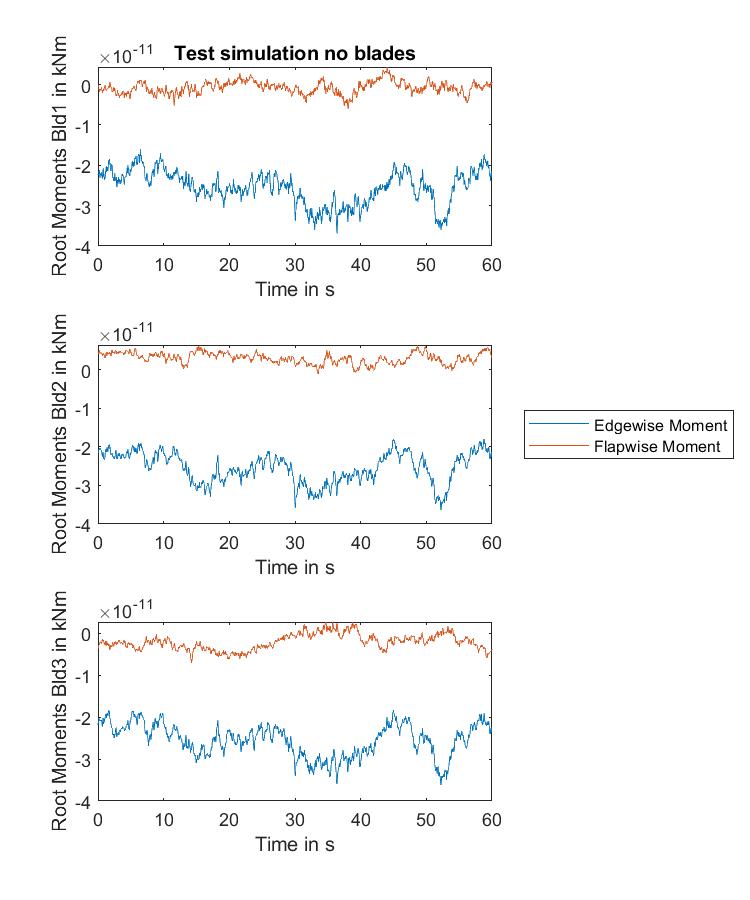
To simulate scenario A, I designed a rotor blade that is very short (0.1m) and very light (BMassDen = 0.0000001 kg/m) and get very low loads on the rotor blades.
To simulate scenario B, I set NumBl = 1 in ElastoDyn for the number of rotor blades and use the rotor blade of the NREL 5 MW Reference Wind Turbine.
However, I have problems with scenario C. Since the positioning of the rotor blades on the hub changes when I use NumBl = 2 (the angle between the rotor blades would be 180° and not 120°), I cannot proceed as I did with scenario A. In addition, the length of the rotor blades is set the same for all via TipRad in ElastoDyn. Therefore, I wanted to proceed similarly to scenario B, in which I use a rotor blade as a third rotor blade that has a very low mass and a low aerodynamic influence. The used values for ElastoDyn and AeroDyn are listed below. For the other two rotor blades I used the rotor blades of the NREl 5 MW reference wind turbine.
ElastoDyn Distributed blade properties:
---------------------- DISTRIBUTED BLADE PROPERTIES ----------------------------
    BlFract      PitchAxis      StrcTwst       BMassDen        FlpStff        EdgStff
      (-)           (-)          (deg)          (kg/m)         (Nm^2)         (Nm^2)
0.0000000E+00  0.0000000E+00  0.0000000E+00  0.0000001E+00  9.9999999E+10  9.9999999E+10
1.0000000E+00  0.0000000E+00  0.0000000E+00  0.0000001E+00  9.9999999E+10  9.9999999E+10
AeroDyn Blade Properties:
======  Blade Properties =================================================================
         2   NumBlNds           - Number of blade nodes used in the analysis (-)
  BlSpn        BlCrvAC        BlSwpAC        BlCrvAng       BlTwist        BlChord          BlAFID
   (m)           (m)            (m)            (deg)         (deg)           (m)              (-)
0.0000000E+00  0.0000000E+00  0.0000000E+00 0.0000000E+00  0.0000000E+00  0.0000001E+00        1
6.1499900E+01  0.0000000E+00  0.0000000E+00 0.0000000E+00  0.0000000E+00  0.0000001E+00        1
The simulation results for the root moments of the three rotor blades are shown in the following figure:
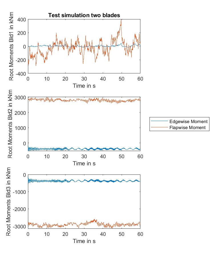
As you can see blade 1 (Bld1) is the adapted rotor blade. I had hoped that the moments acting on the rotor blade would be very small. Does anyone have any idea how I can further reduce the influence of rotor blade 1 (Bld1) and where the high flapwise moments are coming from?
I am using OpenFAST-v3.1.0 on a Windows computer. The modules ElastoDyn, InflowWind, AeroDyn15, HydroDyn and SubDyn are used. For the wind and wave conditions the conditions from the R-Test “5MW_OC3Mnpl_DLL_WTurb_WavesIrr” were used. The turbine is in the parked state.
Thanks for your help and input, if something is not clearly explained or i forgot some informations please ask.
Best regards
Malte