Hello,
I am interested in modelling an 18MW turbine with OpenFAST. I cannot find a reference turbine of this size so I was thinking about scaling up the IEA-15-240-RWT turbine which is publicly available. I noticed that NREL have published a power curve for an 18MW version… [2020ATB_NREL_Reference_18MW_263 — NREL/turbine-models power curve archive 0 documentation]. Apart from increasing the blade lengths and changing the hub height. I am wondering what other changes would be required to the OpenFAST model of the 15MW turbine.
- The individual blade span lengths could be scaled according to the blade length ratio, therefore moving the aerofoil profiles further away from the hub (I am assuming the same aerofoils could be used).
- Blade and hub masses could be upscaled similarly. Blade stiffnesses also.
- Would the chord lengths of the aerofoils need to be scaled also?
- Would the same ROSCO controller also work for the larger turbine? If not, would a new DLL be required or simply some changes to the .IN input file?
I would appreciate any advice from NREL or indeed any contributor who may have some experience in upscaling OpenFAST models.
Kind regards,
Dear @Oisin.Conway,
A similar question regarding scaling was discussed in the following forum topic: 2.5 MW WT.
Regarding your specific questions, I would say “yes” to 1-3, and for 4, I would say that the input file of ROSCO needs to be changed, but the DLL does not need to be changed.
Best regards,
Hi Oisin,
I am doing an upscaling from 15 MW to 20 MW. We can keep contact for some doubts we have. About the blade stiffnesses, did u find any relation to upscale stiffnesses? I am saying this because i have not found any relation. Plus, are u upscaling your turbine linearly or based on statistic methods?
br
Dear @Alberto.Utrera,
If you are referring to pure geometric scaling of the blade cross-sectional bending stiffness (E*I), this would scale with the length^4 (keeping the material properties the same).
Best regards,
Dear @Jason.Jonkman, when you say that bending stiffness scales with length^4, what would it be in terms of mathematic expression?
I suppose what you are referring to is as follows: Let’s suppose we want to do an upscaling from 15 MW to 20 MW, so the scaling factor would be sqrt (20/15)=1,1547. Is it correct if i say that the bending stiffness for the 20 MW wind turbine is going to be the 15 MW stiffness multiplied by (1,1547^4)?
Thank you very much.
Dear @Alberto.Utrera,
No, I meant that cross-sectional stiffness would scale with the length ratio to the fourth power, e.g.:
( bending stiffness for 20-MW turbine ) = ( bending stiffness for 15-MW turbine ) * ( ( blade length for 20-MW ) / ( blade length for 15-MW turbine ) ) ^ 4.
Best regards,
1 Like
Hi again @Jason.Jonkman.
I am already doing the upscaling for the tower (from 15 MW to 20 MW) and i have the following questions:
According to pure geometric scaling, does the tower mass density scales up with the tower length (keeping the material properties the same)? Or it would scale with the scaling factor? By scaling factor, I mean the square root of 20 divided by 15.
Regarding stifnesses (side to side, fore-aft, torsional, axial) and inertias , would these scale up with the tower length^4 (keeping the material properties the same)?
Thanks. BR. ALbert
Dear @Alberto.Utrera,
Here are the pure geometric scaling for cross-sectional mass (mu), bending stiffness (EI), torsional stiffness (GJ), axial stiffness (EA), and inertias (I):
( mu for 20-MW turbine ) = ( mu for 15-MW turbine ) * ( ( blade length for 20-MW ) / ( blade length for 15-MW turbine ) ) ^ 2
( EI for 20-MW turbine ) = ( EI for 15-MW turbine ) * ( ( blade length for 20-MW ) / ( blade length for 15-MW turbine ) ) ^ 4
( GJ for 20-MW turbine ) = ( GJ for 15-MW turbine ) * ( ( blade length for 20-MW ) / ( blade length for 15-MW turbine ) ) ^ 4
( EA for 20-MW turbine ) = ( EA for 15-MW turbine ) * ( ( blade length for 20-MW ) / ( blade length for 15-MW turbine ) ) ^ 2
( I for 20-MW turbine ) = ( I for 15-MW turbine ) * ( ( blade length for 20-MW ) / ( blade length for 15-MW turbine ) ) ^ 4
Best regards,
1 Like
Dear @Jason.Jonkman,
I do not understand why bending stiffnesses scale with an exponent of 4.
I have done a structural analysis and i get that it should be upscaled to the third power. Here it is my proceeding:
To determine the stiffness, it will be assumed that the blades have a constant load along their length, causing a moment at the blade root, which is M=q*L^2/2 (in the following image, there is the beam depicted).

With a constant load along the length of the blade, the deflection at end
“A” can be calculated as follows:

Since the edgewise and flapwise shear is proportional to the distance squared,
we can relate the moments for different machines as follows:

therefore the relationship between loads will be q1/q2=1.
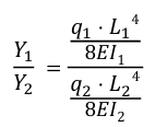
Now that the relationship between loads is known, we can write the equation that relates
the deflections for different turbines :

By subtracting the stiffness ratio from the above expression, we get

So, it has been demonstrated that the ratio of stiffnesses is equal to the ratio of diameters cubed.
BR. Albert
Dear @Alberto.Utrera,
I’m not following all of your arguments, but if you assume the geometry is being scaled while the material properties are kept the same, the Young’s modulus (E) is not scaled while the cross-sectional inertia (I) scales with the 4th power of length. So, EI will also scale with the 4th power of length.
Best regards,
1 Like
Understood, thanks @Jason.Jonkman


