Adapting Baseline IEA 3.4 RWT to a Vestas V100/1800 Wind Turbine

Hello everyone,

My name is Emilio, and I am currently an undergraduate student. I recently started a research internship which focuses on operational modal analysis of wind turbines, and as part of this effort I am planning to model a wind turbine using OpenFAST. I am interested in modelling an onshore Vestas V100/1800 turbine, unfortunately there is not an existing model online for this turbine, as such, I am trying to follow the open-source model development procedure applied in GitHub - NREL/openfast-turbine-models: A repository of OpenFAST turbine models developed by NREL researchers. .

I previously sent an email to an NREL researcher to ask for a recommended baseline model to adapt using this method and he recommended two things:

They then mentioned the following:

  • I should match the power and thrust curves with WISDEM
  • Generate a wind turbine model with WEIS, do a sanity check of the turbine generated by WEIS on the resulting model dynamics.
  • Finally, tweak the constraints such as frequency or blade shape to modify the structural response to make it more realistic.

Now, I have edited the scripts found in the “combined aerostruct opt2” to adapt the IEA 3.4 RWT wind turbine model. Basically, I only changed the starting file for the IEA turbine to have the same hub height, rotor diameter, and rated power as the Vestas to start with, and I also changed the file “tower_struct_opt.py” such that the scaled tower diameter follows the same measurements as the Vestas V100/1800 I am trying to model. I also went into all the analysis and modelling options and made sure that the file references are correct so that I can run the .py files in order without issues. After doing this I got a lot of questions.

  1. I understand that this is the first step in the process where WISDEM will generate an optimized wind turbine model based on the specs I gave. What I don’t understand is how I can make sure I get the power and thrust curves from the process. Am I supposed to change any of my modelling options files to ensure that this data is output?

  2. I noticed the slurm file “mpi_aerostruct_opt.slurm” asks for 8 hours of time to run the optimization and asks python to run the processes with 94 cores. I have set up a Conda environment with WISDEM, WEIS, and OpenFAST in my university’s HPC to run the batch process but I am worried about the size of this simulation because of the amount of time and cores allocated to the process. Is this approach going to generate a massive amount of data? If so in, what range of gigabytes can I expect? Just wanna make sure WISDEM outputs are small since we have limited scratch space at the moment.

  3. I’d like to know if there are more things that can change in my starting geometry besides basic dimensions to match the real turbine better. Is this something I should do in the WISDEM step of the process, or should I make an initial attempt with basic parameters?

  4. Lastly, I also would like to know if there are things I should consider changing in the modelling and analysis files based on my research focus and recommendations I got.

Looking forward to hearing back from users in this forum. I also understand is this process seems too ambitious; I am new to this software so any tutorials I should go through to reach my end goal would also be nice.

Hi Emilio,
welcome to the forum. Your request is not uncommon, and we often find ourselves building OpenFAST models of OEM turbines where we do not have access to the full aero-servo-hydro-elastic model. The activity is however non trivial, and it takes quite a bit of experience to get something together. We do have an internal-only tool that we use, but unfortunately we cannot share it externally. The script that you found can also be useful, but it is not maintained, and I cannot provide specific guidance about it. My recommendation is instead to familiarize yourself with the systems engineering tool WISDEM and its documentation WISDEM ® Documentation — WISDEM 2.0 documentation. The examples provide the fundamental building blocks for a successful redesign. Make sure you take a look at example 16 16. Inverse Design Example — WISDEM 2.0 documentation
Note also that you don’t need large computational resources to get something decent together. A good laptop will be sufficient. No need to spin up 94 cores. The latest WISDEM is more efficient than older versions, and it automatically allocates processes on the available processors. No need to block 94 cores. Also, it’s often a good idea to start from smaller and simpler optimization problems and go up in complexity as you become more familiar with the codes.
I hope this gives you a start.
Best regards

Hi Pietro,

I appreciate the response. I will take a look at the documentation and the provided examples. Thanks for pointing out example 16, it is exactly the type of example I was looking for. I will update on my progress in this thread as I go.

All the best,
Emilio.

Good afternoon @Pietro.Bortolotti

I deleted my previous post as it seems like something more suited to uploading as a WISDEM Github issue.

For the past few weeks I have been playing around with WISDEM and getting a better grasp on how to set up these optimization problems, and in the process I have been able to downscale the IEA-130-RWT turbine rotor into a 100 meter rotor with mixed success. I have been reading concepts from the following sources:

Example 3a and 3b: Blade optimization
Example 16: Rotor Inverse Design Example
WISDEM Github issue #587
And I read some sections of “On the scaling of wind turbine rotors”

From this, I did an an aero-structural optimization using LCOE to see if I could get a good enough downscaled turbine, to then attempt to do an purely aerodynamic optimization in a second separate WISDEM optimization with AEP or Cp as merit figures, and maybe tuning TSR. The process I followed is shown below:

Initially as mentioned in Github Issue 587, I started by changing assembly level values to match the size and power rating of my target turbine:

name: IEA-3.4-130-RWT #to be changed into Vestas model
description: version from December 16th 2019
assembly:
    turbine_class: II #originally was set to III
    turbulence_class: B #originally was set to A
    drivetrain: Geared
    rotor_orientation: Upwind
    number_of_blades: 3
    hub_height: 80. #changed from 110m. Site specific Vestas V100 has this hub height
    rotor_diameter: 100. #changed from 130m
    rated_power: 1.8e+6 #changed from 3.37 MW

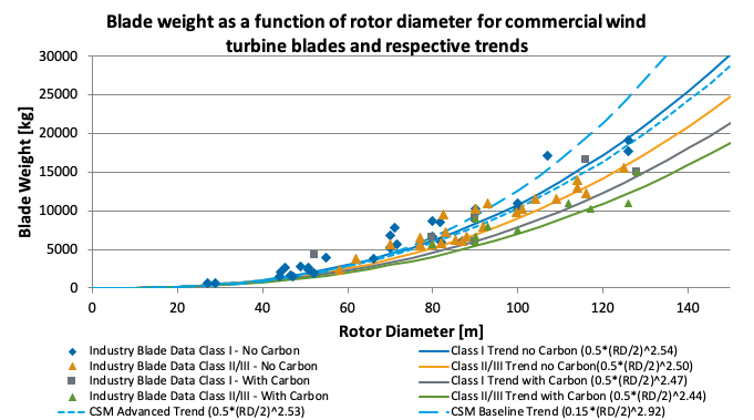
From that, I set up my analysis file to have design variables for aero_shape and structural components, with the main constraints being strains on blade elements, tip deflection, chord size to match something similar to my target turbine, and the blade mass based on what I was able to find about my turbine online and also tried matching it with this source. Notably I tried keeping the settings similar to online examples for constraints which might’ve contributed to the issues I ran into. I kept the optimizer pretty standard, running for max 100 iterations:

general:
    folder_output: outputs_aerostruct 
    fname_output: Vestas-V100-1800_aerostruct

design_variables:
    #deleted rotor diameter design variable as I set the value I want in geometry input file
    blade:
        aero_shape:
            twist:
                flag: True            # Flag to optimize the twist
                inverse: False
                inverse_target: max_efficiency          # Flag to determine twist from the user-defined desired margin to stall (defined in constraints)

                #Here I set twist flag to false, and instead set inverse to true, and set inverse target to max efficiency

                n_opt: 8               # changed from 4 to 10 sections along blade span
                max_decrease: 0.1 # Maximum decrease for the twist in [rad] at the n_opt locations
                max_increase: 0.1 # Maximum increase for the twist in [rad] at the n_opt locations
                index_start: 2         # Lock the first two DVs from blade root
                index_end: 8           # All DVs close to blade tip are active
            chord:
                flag: True             # Flag to optimize the chord
                n_opt: 8               # Number of control points along blade span
                max_decrease: 0.3      # Minimum multiplicative gain on existing chord at the n_opt locations
                max_increase: 3.       # Maximum multiplicative gain on existing chord at the n_opt locations
                index_start: 2         # Lock the first two DVs from blade root
                index_end: 8           #change blade tip chord
        structure:
            - layer_name: Spar_cap_ss
              n_opt: 8               # Number of control points along blade span
              max_decrease: 0.2      # Maximum nondimensional decrease at the n_opt locations
              max_increase: 5.0      # Maximum nondimensional increase at the n_opt locations
              index_start: 1         # Lock the first DV from blade root
              index_end: 8           # The last DV at blade tip
            - layer_name: Spar_cap_ps
              n_opt: 8               # Number of control points along blade span
              max_decrease: 0.2      # Maximum nondimensional decrease at the n_opt locations
              max_increase: 5.0      # Maximum nondimensional increase at the n_opt locations
              index_start: 1         # Lock the first DV from blade root
              index_end: 8           # The last DV at blade tip
            - layer_name: Shell_skin
              n_opt: 8
              max_decrease: 0.2
              max_increase: 5.0
              index_start: 2
              index_end: 8
            - layer_name: LE_reinforcement
              n_opt: 8
              max_decrease: 0.2
              max_increase: 5.0
              index_start: 1
              index_end: 8
            - layer_name: TE_reinforcement_SS 
              n_opt: 8
              max_decrease: 0.2
              max_increase: 5.0 
              index_start: 1 
              index_end: 8
            - layer_name: TE_reinforcement_PS 
              n_opt: 8 
              max_decrease: 0.2 
              max_increase: 5.0 
              index_start: 1 
              index_end: 8

merit_figure: LCOE

constraints:
    blade:
        strains_spar_cap_ss:
            flag: True         # Flag to impose constraints on maximum strains (absolute value) in the spar cap on the blade suction side
            max:    3500.e-6   # Value of maximum strains [-]
            index_start: 1     # Do not enforce constraint at the first station from blade root of the n_opt from spar_cap_ss
            index_end: 7       # Do not enforce constraint at the last station at blade tip of the n_opt from spar_cap_ss
        strains_spar_cap_ps:
            flag: True         # Flag to impose constraints on maximum strains (absolute value) in the spar cap on the blade pressure side
            max:    3500.e-6   # Value of maximum strains [-]
            index_start: 1     # Do not enforce constraint at the first station from blade root of the n_opt from spar_cap_ps
            index_end: 7       # Do not enforce constraint at the last station at blade tip of the n_opt from spar_cap_ps
        strains_te_ss:
            flag: True        # Flag to impose constraints on maximum strains (absolute value) in the spar cap on the blade suction side
            max:    3500.e-6   # Value of maximum strains [-]
            index_start: 1     # Do not enforce constraint at the first station from blade root of the n_opt from spar_cap_ss
            index_end: 7       # Do not enforce constraint at the last station at blade tip of the n_opt from spar_cap_ss
        strains_te_ps:
            flag: True         # Flag to impose constraints on maximum strains (absolute value) in the spar cap on the blade pressure side
            max:    3500.e-6   # Value of maximum strains [-]
            index_start: 1     # Do not enforce constraint at the first station from blade root of the n_opt from spar_cap_ps
            index_end: 7       # Do not enforce constraint at the last station at blade tip of the n_opt from spar_cap_ps
        tip_deflection:
            flag: True
            margin: 2 #higher tip deflection margin chosen as blade deflection was too high
        # stall:
        #     flag: True    # Constraint on minimum stall margin
        #     margin: 0.08722  # Increased stall margin from 0.087 to 0.15
        moment_coefficient:
            flag: True    # Constraint on max aerodynamic moment coefficient
            max: 0.16
        chord:
            flag: True
            max: 4.2 #max chord length in Vestas V100 is 3.9 metres
            min: 0.5  
        chord_slope:
            flag: True
        # rated_velocity:
        #     flag: True
        #     target: 12 #m/sec
        #     acceptable_error: 0.1
        # rated_thrust:
        #     flag: True
        #     target: 520000 #value for other 2MW turbines
        #     acceptable_error: 10000.0
        mass: 
            flag: True
            target: 7500 #expected weight per blade
            acceptable_error: 1000.
    nacelle: 
        mass:
            flag: True
            target: 82000 #AI generated approximate nacelle mass
            acceptable_error: 2000  # Adjust based on design flexibility
    rotor:
        mass:
            flag: True
            target: 22500  # 3 Ă— 7500 blade mass (or calculated rotor mass)
            acceptable_error: 1000
    rna: #rotor nacelle assembly.
        mass:
            flag: True
            target: 116500 #kg from estimated weight of rotor, nacelle, and hub assembly.
            acceptable_error: 3000


driver:
    optimization:
        flag: True         # Flag to enable optimization
        tol: 1.e-5          # Optimality tolerance
        # max_major_iter: 10  # Maximum number of major design iterations (SNOPT)
        # max_minor_iter: 100 # Maximum number of minor design iterations (SNOPT)
        max_iter: 100         # Maximum number of iterations (SLSQP)
        solver: SLSQP       # Optimization solver. Other options are 'SLSQP' - 'CONMIN'
        step_size: 1.e-3    # Step size for finite differencing
        form: forward       # Finite differencing mode, either forward or central

recorder:
    flag: True             # Flag to activate OpenMDAO recorder
    file_name: log_opt.sql # Name of OpenMDAO recorder

After running the simulation I was able to generate the following results:


Overall, I think the results were promising for an initial run, but taking a closer look specifically at the thicknesses of the structural elements in the resulting geometry file I noticed that closer to the tip I start getting negative values, and for some reason my first value of the thicknesses starts at 0 which is odd as I thought I specified the program not to edit the thicknesses there in design variables. I believe the negative values might be occurring either because I set up my design variables and constraints incorrectly, or because the resolution of the finite differencing or number of blade elements is not set up correctly, resulting in weird geometry at the root and tip.

Once again thanks for the help, hopefully I can nail down some of the issues that made the rotor optimization not work as intended and that I am on the right track!

Kind regards,
Emilio.

Hi Emilio,
it looks like you’ve been able to make quite some progress. Some quick observations:
1 - Thrust is at times reported including rotor mass at times excluding rotor mass. WISDEM computes aero thrust, so without rotor mass. If you can, please check whether the target excludes it
2 - You can always lock the DV of the structural layers close to blade tip, for example setting them to 7 when you have 8 DVs
3 - Blade root is a huge part of blade mass. You probably want to make sure that blade root diameter is realistic (usually between 4 and 5% of rotor radius)
4 - The power coefficient seems a little low, although you should check whether you are plotting aerodynamic or electrical Cp. This is a common struggle of LCOE optimization, where the optimizer is not always able to land on solutions at realistically high Cp. I often try to split aero and structural optimizations in two separate loops
Let me know if you have more questions!
Regards

1 Like

Hi @Pietro.Bortolotti,

I really appreciate your responses, your advice has been really helpful to progress through this scaling problem. I will try to follow up on the points you mentioned in your last post:

  1. The rated thrust value I am using in my optimization loop should be purely aerodynamic. I calculated it with a formula used for actuator disk theory where:
    image
    The only value I could find online for this was the swept area of the turbine I am modelling and some Ct vs wind speed data:
  • Ct =0.29 at a 12 m/s wind speed (rated wind speed)
  • row = 1.23 kg/m^3. (sea level air density, my turbine is near sea level)
  • A = 7850 m^2 according to an online source.
    Note that the value I showed in my code snippet in my previous post is outdated, I have that my rated aerodynamic thrust is around 210,000 N

To be honest I am not sure this is the best estimation of my rotor thrust any comments on my calculation would be appreciated.

  1. Noted: Will lock the DV’s at blade tip for structural optimization, I am assuming that their overall mass and frequency content don’t affect the overall result much since most of the material is near the blade root?

  2. Online I was able to find that the blade root outer diameter for my turbine is 1.88 metres which is well below the 4-5% percent size compared to the rotor radius of 100 metres. Should I let WISDEM optimize the blade root diameter on its own or should I attempt to constrain the blade root diameter to that value? Note that I am interested most in the structural dynamic response of the overall turbine. I was thinking for the structural optimization for the rotor and tower to use mass and frequencies as constraints with LCOE as merit figure.

  3. Since you advised to do so I am now separating the aerodynamic and structural into separate loops, I just have questions regarding aerodynamic optimization at the moment:

  • I am attempting to use Cp as the merit figure and have my main targets be rated velocity and rated thrust. However, I have had trouble getting this to converge. I am attempting to change the blade twist to inverse design with a target of max_efficiency, and the chord distribution. Is this a correct approach to attempt to match my turbine’s behaviour or should I try user defined merit figures, constraints, and so on? I am not very familiar with rotor aerodynamics so optimizing this part has been challenging. I also want to note that I have been plotting Cp vs. wind speed, it’s the data that I was able to find online as a reference.

I will leave my analysis_options file below for reference:

general:
    folder_output: VestasV100ID/outputs_aero 
    fname_output: Vestas-V100-1800_aero

design_variables:
    #deleted rotor diameter design variable as I set the value I want in geometry input file
    control: 
      tsr:
        flag: True
        minimum: 6
        maximum: 9
    blade:
        aero_shape:
            twist:
                flag: False            # Flag to optimize the twist
                inverse: True
                inverse_target: 'max_efficiency'          # Flag to determine twist from the user-defined desired margin to stall (defined in constraints)

                #Here I set twist flag to false, and instead set inverse to true, and set inverse target to max efficiency

                n_opt: 10               # changed from 4 to 10 sections along blade span
                max_decrease: 0.2 # Maximum decrease for the twist in [rad] at the n_opt locations
                max_increase: 0.2 # Maximum increase for the twist in [rad] at the n_opt locations
                index_start: 3         # Lock the first two DVs from blade root
                index_end: 10           # All DVs close to blade tip are active
            chord:
                flag: True             # Flag to optimize the chord
                n_opt: 10               # Number of control points along blade span
                max_decrease: 0.4      # Minimum multiplicative gain on existing chord at the n_opt locations
                max_increase: 1.2       # Maximum multiplicative gain on existing chord at the n_opt locations
                index_start: 2         # Lock the first two DVs from blade root
                index_end: 10           #change blade tip chord

merit_figure: Cp

constraints:
    blade:
      stall: 
        flag: True
        margin: 0.08
      chord:
            flag: True
            max: 4.2 
      chord_slope:
            flag: True
      moment_coefficient:
            flag: True    # Constraint on max aerodynamic moment coefficient
            max: 0.22 #increased for aerodynamic optimization, need to decrease for structural optimization
      rated_velocity:
            flag: True
            target: 12 #m/sec
            acceptable_error: 0.1
      rated_thrust:
            flag: True
            target: 210000 #1/2* Ct *row*A*v^2 A is 7850m^2, row is 1.23, Ct at 12 m/s is 0.29
            acceptable_error: 10000.0
        
driver:
    optimization:
        flag: True         # Flag to enable optimization
        tol: 1.e-5          # Optimality tolerance
        # max_major_iter: 10  # Maximum number of major design iterations (SNOPT)
        # max_minor_iter: 100 # Maximum number of minor design iterations (SNOPT)
        max_iter: 100         # Maximum number of iterations (SLSQP)
        solver: SLSQP       # Optimization solver. Other options are 'SLSQP' - 'CONMIN'
        step_size: 1.e-3    # Step size for finite differencing
        form: forward       # Finite differencing mode, either forward or central

recorder:
    flag: True             # Flag to activate OpenMDAO recorder
    file_name: log_opt.sql # Name of OpenMDAO recorder


Kind regards,
Emilio.

Hi Emilio,
You should not let WISDEM optimize quantities that you know. If you know blade root diameter (although I’ve never seen a blade where the 4/5% rule is badly off…), simply set it.
Now to your aerodynamic optimization, I suspect that you are over constraining the problem, and the optimizer can’t find a chord distribution that satisfies all constraints. Do the opposite instead: start by under-constraining your problem, and slowly add constraints one by one. I personally like to use the OpenMDAO recorder and I use this script WISDEM/wisdem/glue_code/gc_RunTools.py at 46b5309a47d7bcc191dab7408a48806f556cc5b5 · WISDEM/WISDEM · GitHub to plot figure of merit, design variables, and constraints as iterations progress.
Let us know if this helps.
Best,
Pietro

Hi Pietro,

So I have run the aerodynamic optimization in the way you mentioned, turning on the constraints one by one and seeing what causes it to fail. With all constraints on except with the stall constraint the optimization is able to complete without a problem. I got the program to work by turning off stall constraint and changing my inverse design to max efficiency instead for the blade twist.

With only the stall constraint on the optimization will always fail which I find very odd. The program will run for many hours and eventually run out of iterations and come back with a failed optimization.

I have a script that creates convergence plots with RunTools.py. I noticed that for the stall margin convergence plot, multiple lines will hover above and below 1, with a margin of error of ± 0.2 . So bound between 1.2 and 0.8 throughout the optimization but a single line will always be at 0, well below the rest of the lines in the graph. I find this result odd, as what I am assuming this is plotting is the stall margin of all blade sections along the length, but one of the blade sections is always hovering at 0 while the rest are close to 1. I am assuming that the reason my stall margin never converges has to do with this, maybe changing the blade sections the twist and chord distribution optimizes could solve this issue but I am not so sure.

Thanks for your patience and guidance,
Emilio

Hi Emilio,
thanks for your persistence here. The issue here is that twist is not associated to any design variable, but you are prescribing a minimum margin to stall that must be respected. You can keep the inverse optimization for the twist and target a specific margin to stall, but keep the constraint to off, or the optimizer will struggle to converge. WISDEM is a little confusing here I must admit.
I hope this helps

1 Like