Hi everyone. I’m currently doing blade design optimization of NREL 5MW wind turbine. Specifically, I modify the chord distribution of SNL61p5m blade, while the twist angle remains the same as the original design. Whenever the chord distribution is modified, the blade structural properties in “NRELOffshrBsline5MW_Blade.dat” is modified using PreComp. However, I noticed that for some certain chord distribution, the OpenFAST simulation may produce the following warnings:
Time: 0 of 700 seconds. FAST_Solution:CalcOutputs_And_SolveForInputs:SolveOption2:AD_CalcOutput:RotCalcOutput:BEMT_CalcOut put(node 19, blade 1):UA_CalcOutput:UA_BlendSteady:Temporarily turning off UA due to high angle of attack or low relative velocity. This warning will not be repeated though the condition may persist. The BEM solution is being turned off due to low TSR. (TSR = 1.8667). This warning will not be repeated though the condition may persist. (See GeomPhi output channel.) FAST_Solution:FAST_AdvanceStates:AD_UpdateStates:BEMT_UpdateStates:UpdatePhi(node 5, blade 1):BEMT_UnCoupledSolve:There is no valid value of phi for these operating conditions: Vx = 12.835, Vy = -1.0111, rlocal = 11.739, theta = 0.87446, geometric phi = 1.6494. This warning will not be repeated though the condition may persist. (See GeomPhi output channel.)
Though the simulation terminates successfully, the output channels demonstrates abnormal behaviour plotted as follows:
About my simulation settings, I’m using OpenFAST v3.5.0 with ElastoDyn and AeroDyn V15. The DLC is NTM with 10-min average wind speed of 11.362 m/s. The initial conditions of ElastoDyn are set as given in the Figure 9-1 of “Definition of a 5-MW Reference Wind Turbine for Offshore System Development”. In AeroDyn, I set AFAeroMod = 2 and SkewMod = 1.
I tried several methods in relevant posters in this forum but still cannot solve the problem. I wonder if anyone has encountered such situation and can share the experience with me on how to avoid such phenomenon. If there is other information that I should provide with, please inform me.
Thank you for your help!
Dear @Tongzhou.Zhang,
What is the response if you disable the effect of the controller by disabling the generator degree of freedom (GenDOF = FALSE) in ElastoDyn? My guess is you’ve changed the rotor enough that the controller is not responding properly (and its parameters would need updating), but I would first check that the response is reasonable for these conditions with fixed rotor speed.
Best regards,
Dear Dr. Jason
Thank you for your kindly response. Following your suggestion, I disabled the GenDOF and I get the following different warnings:
Time: 0 of 700 seconds.
FAST_Solution:CalcOutputs_And_SolveForInputs:SolveOption2:AD_CalcOutput:RotCalcOutput:BEMT_CalcOut
put(node 19, blade 1):UA_CalcOutput:UA_BlendSteady:Temporarily turning off UA due to high angle
of attack or low relative velocity. This warning will not be repeated though the condition may
persist.
FAST_Solution:CalcOutputs_And_SolveForInputs:SolveOption2:AD_CalcOutput:RotCalcOutput:BEMT_CalcOut
put(node 16, blade 1):UA_CalcOutput:Mach number exceeds 0.3. Theory is invalid. This warning will
not be repeated though the condition may persist.
And the structural responses become:
As you can see, the RotSpeed now oscillates strongly around 12 rpm. The OoPDefl and RootMyb1 also shows strong oscillation.
The comparison between the original chord distribution of SNL61p5m blade and my modified chord distribution here. I wonder if such change can influence the behaviour of the controller?
I further noticed one thing:
By changing the 10-min average wind speed from 11.362 m/s to 11 m/s, the warnings are gone and the response time series looks well, even with modified chord distribution. I’m investigating the reason.
I think my problem is solved. It is due to the initial condition in ElastoDyn.
I obtained the initial condition of ElastoDyn in a poster somewhere in this forum as follows:
| WndSpeed |
OoPDefl |
IPDefl |
B1Pitch |
B2Pitch |
B3Pitch |
RotSpeed |
TTDspFA |
TTDspSS |
| (m/s) |
(m) |
(m) |
(deg) |
(deg) |
(deg) |
(rpm) |
(m) |
(m) |
| 3.000 |
0.9890 |
-0.0820 |
0.0000 |
0.0000 |
0.0000 |
6.9720 |
0.0278 |
-0.0004 |
| 4.000 |
1.3159 |
-0.0993 |
0.0000 |
0.0000 |
0.0000 |
7.1830 |
0.0540 |
-0.0024 |
| 5.000 |
1.7103 |
-0.1588 |
0.0000 |
0.0000 |
0.0000 |
7.5060 |
0.0852 |
-0.0056 |
| 6.000 |
2.1517 |
-0.1635 |
0.0000 |
0.0000 |
0.0000 |
7.9420 |
0.1214 |
-0.0100 |
| 7.000 |
2.6592 |
-0.2925 |
0.0000 |
0.0000 |
0.0000 |
8.4690 |
0.1615 |
-0.0152 |
| 8.000 |
3.2292 |
-0.3295 |
0.0000 |
0.0000 |
0.0000 |
9.1560 |
0.2080 |
-0.0210 |
| 9.000 |
3.9660 |
-0.4173 |
0.0000 |
0.0000 |
0.0000 |
10.2960 |
0.2669 |
-0.0265 |
| 10.000 |
4.7325 |
-0.4516 |
0.0000 |
0.0000 |
0.0000 |
11.4310 |
0.3322 |
-0.0326 |
| 10.100 |
4.8159 |
-0.4900 |
0.0000 |
0.0000 |
0.0000 |
11.5471 |
0.3390 |
-0.0333 |
| 10.200 |
4.9019 |
-0.4950 |
0.0000 |
0.0000 |
0.0000 |
11.6600 |
0.3460 |
-0.0339 |
| 10.300 |
4.9659 |
-0.4897 |
0.0000 |
0.0000 |
0.0000 |
11.7300 |
0.3521 |
-0.0347 |
| 10.400 |
5.0214 |
-0.4968 |
0.0000 |
0.0000 |
0.0000 |
11.7500 |
0.3575 |
-0.0357 |
| 10.500 |
5.0778 |
-0.5061 |
0.0000 |
0.0000 |
0.0000 |
11.7700 |
0.3628 |
-0.0367 |
| 10.600 |
5.1348 |
-0.5169 |
0.0000 |
0.0000 |
0.0000 |
11.7992 |
0.3682 |
-0.0376 |
| 10.700 |
5.1930 |
-0.5286 |
0.0000 |
0.0000 |
0.0000 |
11.8200 |
0.3737 |
-0.0386 |
| 10.800 |
5.2514 |
-0.5403 |
0.0000 |
0.0000 |
0.0000 |
11.8400 |
0.3791 |
-0.0396 |
| 10.900 |
5.3101 |
-0.5512 |
0.0000 |
0.0000 |
0.0000 |
11.8700 |
0.3846 |
-0.0406 |
| 11.000 |
5.3692 |
-0.5610 |
0.0000 |
0.0000 |
0.0000 |
11.8900 |
0.3901 |
-0.0416 |
| 11.100 |
5.4285 |
-0.5697 |
0.0000 |
0.0000 |
0.0000 |
11.9166 |
0.3957 |
-0.0427 |
| 11.200 |
5.4880 |
-0.5776 |
0.0000 |
0.0000 |
0.0000 |
11.9400 |
0.4013 |
-0.0437 |
| 11.300 |
5.5471 |
-0.5853 |
0.0000 |
0.0000 |
0.0000 |
11.9650 |
0.4069 |
-0.0448 |
| 11.400 |
5.4226 |
-0.6188 |
0.6017 |
0.6017 |
0.6017 |
12.1000 |
0.3987 |
-0.0450 |
| 11.500 |
5.1487 |
-0.6513 |
1.4519 |
1.4519 |
1.4519 |
12.1000 |
0.3794 |
-0.0452 |
| 11.600 |
4.9556 |
-0.6718 |
2.0784 |
2.0784 |
2.0784 |
12.1000 |
0.3661 |
-0.0453 |
| 11.700 |
4.8003 |
-0.6866 |
2.5918 |
2.5918 |
2.5918 |
12.1000 |
0.3556 |
-0.0454 |
| 11.800 |
4.6661 |
-0.6981 |
3.0427 |
3.0427 |
3.0427 |
12.1000 |
0.3467 |
-0.0455 |
| 11.900 |
4.5468 |
-0.7074 |
3.4495 |
3.4495 |
3.4495 |
12.1000 |
0.3389 |
-0.0455 |
| 12.000 |
4.4382 |
-0.7149 |
3.8230 |
3.8230 |
3.8230 |
12.1000 |
0.3319 |
-0.0456 |
| 13.000 |
3.6501 |
-0.7404 |
6.6020 |
6.6020 |
6.6020 |
12.1000 |
0.2844 |
-0.0460 |
| 14.000 |
3.1155 |
-0.7307 |
8.6680 |
8.6680 |
8.6680 |
12.1000 |
0.2550 |
-0.0462 |
| 15.000 |
2.6880 |
-0.7051 |
10.4500 |
10.4500 |
10.4500 |
12.1000 |
0.2333 |
-0.0463 |
| 16.000 |
2.3278 |
-0.6693 |
12.0550 |
12.0550 |
12.0550 |
12.1000 |
0.2165 |
-0.0464 |
| 17.000 |
2.0138 |
-0.6259 |
13.5360 |
13.5360 |
13.5360 |
12.1000 |
0.2030 |
-0.0465 |
| 18.000 |
1.7327 |
-0.5759 |
14.9200 |
14.9200 |
14.9200 |
12.1000 |
0.1921 |
-0.0466 |
| 19.000 |
1.4765 |
-0.5203 |
16.2260 |
16.2260 |
16.2260 |
12.1000 |
0.1832 |
-0.0467 |
| 20.000 |
1.2452 |
-0.4616 |
17.4730 |
17.4730 |
17.4730 |
12.1000 |
0.1758 |
-0.0467 |
| 21.000 |
1.0430 |
-0.4042 |
18.6990 |
18.6990 |
18.6990 |
12.1000 |
0.1691 |
-0.0467 |
| 22.000 |
0.8829 |
-0.3563 |
19.9410 |
19.9410 |
19.9410 |
12.1000 |
0.1625 |
-0.0467 |
| 23.000 |
0.7387 |
-0.3082 |
21.1770 |
21.1770 |
21.1770 |
12.1000 |
0.1568 |
-0.0467 |
| 24.000 |
0.5904 |
-0.2514 |
22.3470 |
22.3470 |
22.3470 |
12.1000 |
0.1525 |
-0.0467 |
| 25.000 |
0.4404 |
-0.1875 |
23.4690 |
23.4690 |
23.4690 |
12.1000 |
0.1487 |
-0.0466 |
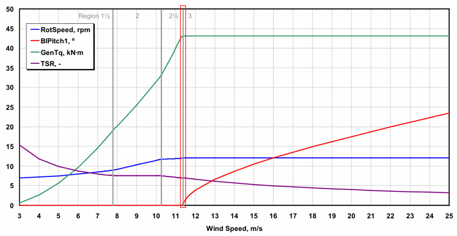
Then, for given U10, the initial conditions are obtained by linear interpolation using the table above. However, when U10 is between 11.3 and 11.4 m/s, linear interpolation may not be accurate. Anyway, what I’m doing is to add a sample from Figure 9-1 of NREL 5MW turbine design report at U10 = 11.35 m/s, and the problem seems to vanish.
I don’t know much about the controllers. I guess the highlighted gray line, which represents a change of controller behaviour lies in 11.3~11.4 m/s? This might the reason why linear interpolation is not accurate in this range.
Dear @Tongzhou.Zhang,
Given that you redesigned the rotor, the published steady-state response of the NREL 5-MW baseline turbine and the gains used in the baseline controller are likely no longer valid. My guess is that you’d have to update the gains used by the controller and regenerate the steady-state response table. If you are not familiar, you can learn about how the original gains were set in the NREL 5-MW baseline turbine’s specifications report: https://www.nrel.gov/docs/fy09osti/38060.pdf.
Best regards,