Dear OpenFAST-Community,
I am trying to increase my understanding of the basic parameters and possibilities of OpenFAST and the Aerodyn Stand-Alone driver.
Maybe some answers are obvious but here are my questions about the output parameters for a standard case by considering only the aerodynamics and the nodes in Aerodyn. I have run the “ad_BAR_CombinedCases” reg test through the AerodynDriver. The parameters were not changed. I am using the Compiled Version AeroDyn_Driver_v3.4.1.
Questions:
-
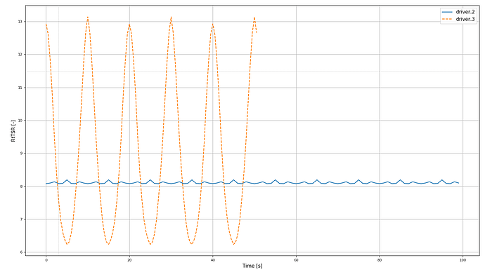
Why does the total speed ratio oscillate with time (see appednix)? Since the wind speed (HWindSpeedX) as well as the rotation speed (RtSpeed*Radius) are constant, shouldn’t the TSR-number also be constant over time?
-
Why does the Reynolds number changes along radial direction of the rotor. Since there is a constant wind speed, shouldn’t the Reynolds number be the same everywhere? Or is it dependent on the rotational speed of every radial position?
-
How can I increase the number of blade nodes in radial- and airfoil-chord-direction?
→ For radial-direction: Do I need a pre-processor to generate or modify the Aerodyn input files “Aerodyn15_Polar_00.dat”, “Coords.txt” and “AeroDyn15_blade.dat” to increase the number of nodes in radial direction?
→ For airfoil-chord-direction: Is it even possible to calculate for example pressure and velocity at different positions of an airfoil? For example, the different pressure coefficients at the leading edge and at the trailing edge of a profile.
-
How can I plot static stall for this example (AoA to cl)? Maybe vary manually the angle of attack (via pitch adjustment) of the blades and observe the lift coefficient cl at a specific node point at blade 1?
Appendix:
I am looking forward to your answer and thank you already!
Best Regards,
Jason
Dear @Jason.Printezis,
Here are my answers to your questions:
- For case 2, this is the result of the 6deg shaft tilt and the way in which the disk-averaged wind speed (used in the calculation of
RtTSR) is calculated by AeroDyn by computing flow normal to the rotor and averaging the ambient wind velocities across each node of each blade. For case 3, the shaft tilt is still there, and in addition, the case has a power-law shear and forced oscillation of surge motion.
- Yes, the local Reynolds number at each blade analysis node depends on the rotational speed and radial position of the node.
- The number and location of the blade nodes in the radial direction are defined within the OpenFAST_BAR_00_AeroDyn15_blade.dat file for this example. You’ll have to select the airfoil data to use at the new analysis nodes (input
BlAFID). AeroDyn uses an actuator line formulation and only has one node in the chordwise direction at each blade station. AeroDyn does not calculate the pressure distribution along the chord, rather, AeroDyn uses the airfoil polar data (Cl, Cd, and Cm versus AoA) to calculate the aerodynamic loads at each analysis node.
- The airfoil polar data at each blade analysis node is specified via input
BlAFID in the AeroDyn blade input file. This corresponds to the index in the AFNames table in the AeroDyn primary input file. The airfoil polar data is set within the corresponding AFNames file. For example, blade node 2 in this example has BlAFID = 2, which corresponds to AFNames(2) = “…/BAR_Baseline/Airfoils/BAR0_AeroDyn15_Polar_01.dat”, so, the airfoil data used at blade node 2 is found in the “…/BAR_Baseline/Airfoils/BAR0_AeroDyn15_Polar_01.dat” file.
Best regards,
1 Like
Dear @Jason.Jonkman,
thanks a lot for asnwering my questions!
Regarding question 3: How can I add nodes to the OpenFAST_BAR_00_AeroDyn15_blade.dat file? More precisely, how can I calculate the relevant parameters of an airfoil as a function of polar coordinates? Is there a special tool / pre-processor?
Best Regards
Jason
Dear @Jason.Printezis,
Adding blade aerodynamic nodes to AeroDyn simply requires increasing NumBlNds and adding associated lines to the table of distributed aerodynamic properties in the AeroDyn blade input file. Often interpolating the geometry and using nearest neighbor airfoil data is sufficient. You could also interpolate the airfoil data, which appears to be what is done already in this design.
That said, please note that the OpenFAST_BAR_00_AeroDyn15_blade.dat file already uses NumBlNds = 30, which is likely more than enough nodes for accurate convergence of a BEM solution, so, I don’t really see a need to increase the number of aerodynamic analysis nodes in this model.
I’m not sure what you mean by “relevant parameters of an airfoil as a function of polar coordinates”? Are you asking how to derive the airfoil coefficients (lift, drag, pitching moment) as a function of AoA?
Best regards,
1 Like
Dear @Jason.Jonkman,
that s correct. I am asking how to derive the airfoil coefficients (lift, drag, pitching moment) as a function of AoA.
I assume that there must be a specific tool to calculate this dependency. I noticed that in the file BAR0_AeroDyn15_Polar_00.dat the AeroElasticSE FAST driver is mentioned. Is this the tool that is used to calculate the dependency?
Best regards
Jason
Dear @Jason.Printezis,
I was not the one who developed this BAR model, but I would guess AirfoilPreppy was used (through AeroElasticSE) to apply 3D corrections (rotational augmentation, stall delay, extrapolation to 360 degrees of AoA) to the 2D airfoil data: GitHub - WISDEM/AirfoilPreppy: A Python module for preprocessing and evaluating aerodynamic airfoil data---primarily for wind turbine applications..
Best regards,
1 Like
All right. Thank you very much again @Jason.Jonkman !
