Dear Yajun,
I’m not sure, but perhaps the numbering of the lines in MAP++ is effected by the location of the specified line and the use of the “repeat” option for the other two lines. Do you get the response you expect if you prescribe all six nodes and all three lines directly within the MAP++ input file?
Best regards,
Hi Jason,
I tried to specific the MAP input file with full properties of the 3 lines:
---------------------- LINE DICTIONARY ---------------------------------------
LineType Diam MassDenInAir EA CB
[-] [m] [kg/m] [N] [-]
Material 0.09 77.7066 384.243E6 0.001 1.0E8 0.6 -1.0 0.05
---------------------- NODE PROPERTIES ---------------------------------------
Node Type X Y Z M B FX FY FZ
[-] [-] [m] [m] [m] [kg] [mˆ3] [N] [N] [N]
1 fix 853.87 0 depth 0 0 # # #
2 Vessel 5.2 0 -70.0 0 0 # # #
3 fix -426.9350 739.4731 depth 0 0 # # #
4 Vessel -2.6000 4.5033 -70.0000 0 0 # # #
5 fix -426.9350 -739.4731 depth 0 0 # # #
6 Vessel -2.6000 -4.5033 -70.0000 0 0 # # #
---------------------- LINE PROPERTIES ---------------------------------------
Line LineType UnstrLen NodeAnch NodeFair Flags
[-] [-] [m] [-] [-] [-]
1 Material 902.2 1 2 tension_fair tension_anch
2 Material 902.2 3 4 tension_fair tension_anch
3 Material 902.2 5 6 tension_fair tension_anch
---------------------- SOLVER OPTIONS-----------------------------------------
Option
[-]
repeat 240 120
And I got the error:
Timestep: 8 of 3000 seconds. Estimated final completion at 17:13:46.
FAST_Solution:CalcOutputs_And_SolveForInputs:SolveOption2:InflowWind_CalcOutput:CalcOutput:IfW_Uni
formWind_CalcOutput:GetWindSpeed:Height must not be negative.
IfW_UniformWind_CalcOutput: Error calculating the wind speed at position (4.3404, -1.98360E-02,
-1.39375E-02) in the wind-file coordinates
FAST encountered an error at simulation time 8.2875 of 3000 seconds.
Simulation error level: FATAL ERROR
Aborting FAST.
I also tried to change the “repeat” option from 240 120 to 120 0 with the previous change of node coordination, but it didn’t work. Would you suggest me to do any other modification of the input file? Thank you very much.
Best regards,
Yajun
Dear Yajun,
When specifying all six nodes and three lines, you should eliminate the repeat option altogether.
Best regards,
Dear Jason,
I’m sorry to bother again. I tried your solution, specifying the full line properties and delete the angle of “option” by the following input content:
---------------------- LINE DICTIONARY ---------------------------------------
LineType Diam MassDenInAir EA CB CIntDamp Ca Cdn Cdt
(-) (m) (kg/m) (N) (-) (Pa-s) (-) (-) (-)
Material 0.09 77.7066 384.243E6 0.001 1.0E8 0.6 -1.0 0.05
---------------------- NODE PROPERTIES ---------------------------------------
Node Type X Y Z M B FX FY FZ
[-] [-] [m] [m] [m] [kg] [mˆ3] [N] [N] [N]
1 fix -426.9350 739.4731 depth 0 0 # # #
2 Vessel -2.6000 4.5033 -70.0000 0 0 # # #
3 fix -426.9350 -739.4731 depth 0 0 # # #
4 Vessel -2.6000 -4.5033 -70.0000 0 0 # # #
5 fix 853.87 0 depth 0 0 # # #
6 Vessel 5.2 0 -70.0 0 0 # # #
---------------------- LINE PROPERTIES ---------------------------------------
Line LineType UnstrLen NodeAnch NodeFair Flags
[-] [-] [m] [-] [-] [-]
1 Material 902.2 1 2 tension_fair tension_anch
2 Material 902.2 3 4 tension_fair tension_anch
3 Material 902.2 5 6 tension_fair tension_anch
---------------------- SOLVER OPTIONS-----------------------------------------
Option
[-]
However, the result shows that it is still the line in 0 degree to be broken.
I also tried to compile the source code as:
DO i = 1,2
	IF (t<100) THEN
	y%ptFairleadLoad%Force(1,i) = -y%FX(i)
	y%ptFairleadLoad%Force(2,i) = -y%FY(i)
	y%ptFairleadLoad%Force(3,i) = -y%FZ(i)
	ELSE
	y%ptFairleadLoad%Force(1,i) = 0
	y%ptFairleadLoad%Force(2,i) = 0
	y%ptFairleadLoad%Force(3,i) = 0
	END IF
	END DO
	DO i = 3,y%ptFairleadLoad%NNodes
	y%ptFairleadLoad%Force(1,i) = -y%FX(i)
	y%ptFairleadLoad%Force(2,i) = -y%FY(i)
	y%ptFairleadLoad%Force(3,i) = -y%FZ(i)
	END DO
But it didn’t work.
Best regards,
Yajun
Dear Yajun,
When you say you that it “didn’t work”, you mean that with your source code changes, you see the tension of line 3 (connecting nodes 5 and 6) going to zero, and the others not? I don’t really see how this is possible given your code change, where you are setting the tensions of lines 1 and 2 to zero. I suggest running the model in debug mode to see what the problem may be.
Best regards,
Dear Jason,
I disabled one of the mooring lines using the previous code modification, the output tension value seems reasonable. However, when I tried to plot the trace of the platform by correlating surge and sway, the figure shows that when line#1(directed alone the positive x axis) is disconnected, the turbine drifts away alone the positive x direction(as I attached below). As my speculation, the platform should move towards the opposite direction to the broken line, could you please help to explain?
Best regards
Yajun
Dear Yajun,
Can you share the MAP++ input file you are using? The input file you posted in your Apr 02, 2019 post above has line 1 upwind (negative X) and to the left (positive Y) when looking downwind.
Best regards,
Dear Jason,
Thank you for your reply. The MAP++ file I used is:
---------------------- LINE DICTIONARY ---------------------------------------
LineType Diam MassDenInAir EA CB CIntDamp Ca Cdn Cdt
(-) (m) (kg/m) (N) (-) (Pa-s) (-) (-) (-)
Material 0.09 77.7066 384.243E6 0.001 1.0E8 0.6 -1.0 0.05
---------------------- NODE PROPERTIES ---------------------------------------
Node Type X Y Z M B FX FY FZ
(-) (-) (m) (m) (m) (kg) (mˆ3) (N) (N) (N)
1 fix 853.87 0 depth 0 0 # # #
2 Vessel 5.2 0 -70.0 0 0 # # #
---------------------- LINE PROPERTIES ---------------------------------------
Line LineType UnstrLen NodeAnch NodeFair Flags
(-) (-) (m) (-) (-) (-)
1 Material 902.2 1 2 tension_fair tension_anch
---------------------- SOLVER OPTIONS-----------------------------------------
Option
(-)
repeat 240 120
I think by using the above mooring properties, the broken line should be the one directed to the positive x-axis.
Best regards,
Yajun
Dear Yajun,
Yes, I agree that it line one is directed downwind, so, I would have guess that eliminating that line would shift the platform upwind. It has hard to tell what is going on without examining other output channels. I would suggest scanning through other outputs to ascertain what is happening or using the visualization functionality of OpenFAST to animate the response.
Best regards,
Dear Jason,
Sorry for the late reply. I just fixed the previous problem, which was a coding mistake. However a new question is that, the tension of the line with zero y%ptFairleadLoad%Force(:,i) increases at the broken time rather than drop to 0, is that reasonable?
Best regards,
Yajun
Dear Yajun,
When you zeroed out the fairlead load by customizing the source code, you didn’t actually modify how the mooring line was modeled in MAP++, correct? Thus, while FAST does not feel the tension of the mooring line that has failed, the tension in the line as calculated by MAP++ is not actually zero, correct?
Best regards,
Dear Jason,
I have never recompiled, but I saw some help about it on the forum.
But I wonder, is it simply possible to directly edit FASTv8\Source\dependencies\MAP\MAP.f90 with a text editor (Notepad++)?
Also, the tension of the line (between the platform and the fairlead) is actually the tension of the fairlead, is that right?
In the MAP++ input file, what is fix, connect, and vessel exactly for the nodes?
Thank you for your help,
Best regards,
Bertrand
Dear Bertrand,
Yes, you can edit the source files with any text editor. Of course, you will need a compiler to compiler.
Yes, the line tension at the fairlead is the tension of the fairlead.
In MAP++, “fix”, “vessel”, and "connect represent the boundary conditions at the end of a line:
- “fix” can be considered an anchor (fixed to the inertial frame);
- “vessel” can be considered a fairlead (where the line connects to the platform/vessel);
- "connect represents a line-to-line interconnection.
I hope that helps.
Best regards,
Dear Jason,
Thank you for your answer.
So to do load case 3.7, I did edit the MAP.F90 source file lie the following:
DO i = 1,2
IF (t<100) THEN
y%ptFairleadLoad%Force(1,i) = -y%FX(i)
y%ptFairleadLoad%Force(2,i) = -y%FY(i)
y%ptFairleadLoad%Force(3,i) = -y%FZ(i)
ELSE
y%ptFairleadLoad%Force(1,i) = 0
y%ptFairleadLoad%Force(2,i) = 0
y%ptFairleadLoad%Force(3,i) = 0
END IF
END DO
DO i = 3,y%ptFairleadLoad%NNodes
y%ptFairleadLoad%Force(1,i) = -y%FX(i)
y%ptFairleadLoad%Force(2,i) = -y%FY(i)
y%ptFairleadLoad%Force(3,i) = -y%FZ(i)
END DO
with this MAP input file:
---------------------- LINE DICTIONARY ---------------------------------------
LineType Diam MassDenInAir EA CB CIntDamp Ca Cdn Cdt
(-) (m) (kg/m) (N) (-) (Pa-s) (-) (-) (-)
Material 0.0766 113.35 7.536E8 1.0 0 0 0 0
---------------------- NODE PROPERTIES ---------------------------------------
Node Type X Y Z M B FX FY FZ
(-) (-) (m) (m) (m) (kg) (mˆ3) (N) (N) (N)
1 fix 837.6 0 depth 0 0 # # #
2 Vessel 40 0 -14.0 0 0 # # #
---------------------- LINE PROPERTIES ---------------------------------------
Line LineType UnstrLen NodeAnch NodeFair Flags
(-) (-) (m) (-) (-) (-)
1 Material 835.35 1 2 tension_fair tension_anch
---------------------- SOLVER OPTIONS-----------------------------------------
Option
(-)
repeat 240 120
and I obtain this Surge (x-axis) Sway (y-axis) chart, which seems totally wrong:
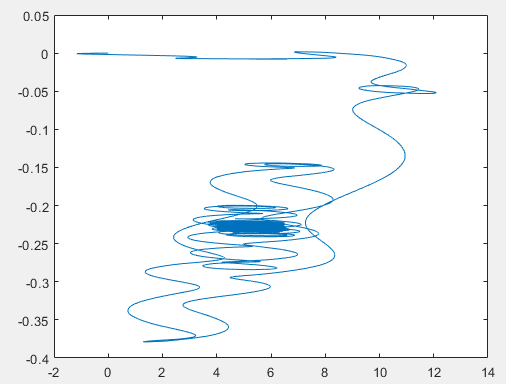
with the fairlead tension of line 1 never equal to zero (T1 y-axis, time x-axis):
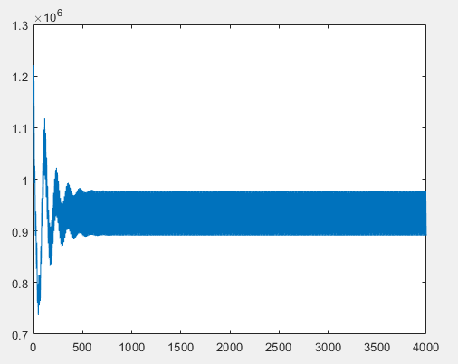
It is like the source code modification was not taken into account.
Do you have an idea why? Probably because I did not “compile” it. I am not familiar at all with this.
Thank you for your help,
Bertrand
Dear Bertrand,
When you change the source code, you’ll need to recompile for the changes to take effect.
Best regards,
Dear Jason and all,
I am trying to implement a transitional event of mooring line loss for DTU 10MW floating model. Based on the inputs from this discussion I have tried to modify the source code for MoorDyn but the result is not as expected. Could anyone correct me where I am going wrong?
P.S. Relatively I have zero skills in coding.
“DO I = 1, p%NFairs
DO J = 1,3
IF (t>=100) THEN
m%ConnectList(m%FairIdList(I))%r(J) = 0%PtFairleadDisplacement%Position(J,I) + 0%PtFairleadDisplacement%TranslationDisp(J,I)
m%ConnectList(m%FairIdList(I))%rd(J) = 0%PtFairleadDisplacement%TranslationVel(J,I) ! is this right? <<<
ELSE
m%ConnectList(m%FairIdList(I))%r(J) = u%PtFairleadDisplacement%Position(J,I) + u%PtFairleadDisplacement%TranslationDisp(J,I)
m%ConnectList(m%FairIdList(I))%rd(J) = u%PtFairleadDisplacement%TranslationVel(J,I) ! is this right? <<<
ELSE IF
DO I = 2,3, p%NFairs
DO J = 1,3
m%ConnectList(m%FairIdList(I))%r(J) = u%PtFairleadDisplacement%Position(J,I) + u%PtFairleadDisplacement%TranslationDisp(J,I)
m%ConnectList(m%FairIdList(I))%rd(J) = u%PtFairleadDisplacement%TranslationVel(J,I) ! is this right? <<<
END DO
END DO”
Thanks and regards
Abhinay Goga
1 Like
Dear Abhinay,
You’re on the right track, but I think you’ll need to study more about FORTRAN coding, and figure out more about the MoorDyn code, before you’ll be able to succeed.
Here are a couple tips:
- To set a value to zero, you can use “=0.0_ReKi”, for example: m%ConnectList(m%FairIdList(I))%r(J) = 0.0_ReKi,
- The values your code would set to zero are the fairlead displacements, but I think what you want to do is set the fairlead forces to zero.
There is a bit of discussion about the idea of simulating failures in MoorDyn in this thread, in case it’s helpful to you: Making fault
Best,
Matt
Dear Matt,
Yes. The main objective is to call zero tension on one fairlead after certain run time to make it perform like line loss. After going through the thread that you have attached, now I understood that Fairlead nodal positions and loads are called from subroutine DoLineRHS. With my limited knowledge in coding I tried to change the inputs for final loads in the following way.
" ! add force and mass of end nodes to the Connects they correspond to
DO J = 1,3
IF (t>=100) THEN
FairFtot(1) = 0.0_ReKi
AnchFtot(1) = 0.0_ReKi
FairFtot(2) = FairFtot(2) + Line%F(2,N)
AnchFtot(2) = AnchFtot(2) + Line%F(2,0)
FairFtot(3) = FairFtot(3) + Line%F(3,N)
AnchFtot(3) = AnchFtot(3) + Line%F(3,0)
ELSE
FairFtot(J) = FairFtot(J) + Line%F(J,N)
AnchFtot(J) = AnchFtot(J) + Line%F(J,0
DO K = 1,3
FairMtot(K,J) = FairMtot(K,J) + Line%M(K,J,N)
AnchMtot(K,J) = AnchMtot(K,J) + Line%M(K,J,0)
END DO
END DO "
Yet it is still not performing in the expected manner. Could you please guide me where I am making wrong this time.
Thanks and regards
Abhinay Goga
Dear Abhinay,
It looks like your code is zeroing out the X-component force for the fairleads and anchors of all lines. DoLineRHS is called separately for each line, and the three entries of the FairFtot array correspond to the X, Y, and Z force components. FairFtot corresponds to forces at the fairlead, AnchFtot corresponds to forces at the anchor. The current mooring line number can be found in DoLineRHS with the variable Line%IdNum.
If you want to simulate the failure of one line at the fairlead, I would suggest the following:
- expand your “if” condition to include both the failure time (t>=100) and which line fails (Line%IdNum==1 for example)
- if the condition is true, zero out all components (X,Y,Z) of the fairlead force vector and mass matrix
I’ve included an (untested) example below. Let me know how it goes.
Matt
IF ((t>=100) .and. (Line%IdNum==1)) then
DO J = 1,3
FairFtot(J) = 0.0_Reki
AnchFtot(J) = AnchFtot(J) + Line%F(J,0)
DO K = 1,3
FairMtot(K,J) = 0.0_ReKi
AnchMtot(K,J) = AnchMtot(K,J) + Line%M(K,J,0)
END DO
END DO
else
DO J = 1,3
FairFtot(J) = FairFtot(J) + Line%F(J,N)
AnchFtot(J) = AnchFtot(J) + Line%F(J,0)
DO K = 1,3
FairMtot(K,J) = FairMtot(K,J) + Line%M(K,J,N)
AnchMtot(K,J) = AnchMtot(K,J) + Line%M(K,J,0)
END DO
END DO
end if
Dear Matt and Jason,
Thanks for the assistance. While recompiling FAST v8 using Visual studio there are errors and few warnings .
I just changed the source code as suggested in dependencies/MoorDyn.
Any assistance with resolving these would be appreciated.
Thanks and reagards
Abhinay Goga
Recompiling issues.txt (19.7 KB)
