Dear all,
I’m a bit confused about the different line tension outputs from MoorDyn.
What I have clarified myself is, that the tension which one could request with the L#N@Ten syntax in the output section of the MoorDyn input file is actually the tension of the line segment preceding the requested node @, i.e. L#N@Ten is the same tension one gets by using the flag t in the Line Properties section of the MoorDyn input file. This is also verified by the MoorDyn developer Matt at https://github.com/OpenFAST/openfast/pull/604#issuecomment-735524446.
However, it is still not clear to me, what’s the difference between the tension at a connect node and that of a line segment?
In [1] it is mentioned that
I thought, that this might mean, that the tension at the connect node is the sum of the tensions of the neighbouring line segments, but that’s obviously not the case - at least not in the test cases I run.
Could someone tell me what’s the difference of the tension at a connect node and of a line segment and how the tension at a connect node is calculated?
Furthermore, when I run a MoorDyn simulation to check if my mooring line withstands the occuring forces, which tension output should I take to compare with the breaking load of the cable?
Thanks a lot in advance.
Best regards,
Paul Schünemann
[1] Vissio, G. et al.: „Expanding ISWEC Modelling with a Lumped-Mass Mooring Line Model.“ In: The European Wave and Tidal Energy Conference, Nantes, France (2015). Available at https://matt-hall.ca/docs/vissio_2015_eim.pdf
Hi Paul,
To start with, I must admit that I wrote most of the current MoorDyn module in OpenFAST years ago as a side project during my PhD, and I did a hasty job with the optional outputs. Most of the refinements I made since then were to the standalone/C++ version, and it’s only since I joined NREL last year that I’m again working on the OpenFAST module version. So improvements are definitely needed in some of these outputs.
The tension channels in the line output files (enabled with a “t”) provide the tension of each segment along the line due only to stiffness, i.e. F_ten = EA*((L-L_0) / L_0), where L_0 is the segment’s unstretched length. This excludes the contribution of structural damping to the true segment tension, which can be output separately with the letter “c”.
The custom tension outputs along a line in the main output file (e.g. “L1N4Ten”) currently give the tension of the segment prior to that node, as you say. Like the tension outputs in the line output files, this is just the stiffness component and does not include the damping component. In the upcoming version 2, this output will be changed so that it gives the total tension at the node itself – an update I already made in MoorDyn C++/standalone.
MoorDyn calculates tensions at the end of a line, as applied on a connection, by summing all forces on the line’s end node. This includes internal stiffness and damping as well as weight and hydrodynamic loads. However, the net force output at a connection will include the vector sum from all attached lines, so it only gives a measure of tension in the case of fairlead or anchor connections where just a single line is attached.
The sentence you quoted refers to the fact that the dynamics of a free connection point are calculated using the sum of these forces on the ends of each attached line, as well as the sum of the lumped mass at the end of each line.
I hope these clarifications resolve your questions. In practice, if your discretization is fine enough, using the segment tension outputs along a line should usually be adequate for capturing the line tensions. That said, if you want to focus on the tension at the fairlead and have only one line attached per fairlead, taking the net force on the connection (Con#Ten where # is connection number, or equivalently FairTen# where # is line number) may give you a slightly more accurate result. If you are seeing situations where the tension on a fairlead connection is significantly different from the tension on the line’s last segment, please let me know.
Best,
Matt
Hi Matt,
thank you very much for your quick and comprehensive reply.
I just have some follow-up questions, mainly to make shure I get all things right.
You are mentioning that “if your discretization is fine enough, using the segment tension outputs along a line should usually be adequate for capturing the line tensions.”
Does that mean, that if the discretization is fine enough the damping force (output with flag “c”) is very small and thus could be neglected and that’s the reason why the segment tension output is an adequate output for capturing the line tensions?
That said, am I right that using the sum of the segment tension output (flag “t”) plus the damping force (output with flag “c”) would be an even more accurate measure of the line tension?
Additionally, how could one determine whether the discretization is fine enough or not? Could I draw the relation, that if the damping force (flag “c”) is almost zero, the discretization should be fine enough?
Additionally, you wrote “However, the net force output at a connection will include the vector sum from all attached lines, so it only gives a measure of tension in the case of fairlead or anchor connections where just a single line is attached.”
I guess with net force here you mean the output of Con#Ten, right? I wonder a bit, as this description sounds very similar to the description of what one theoretically could get with Con#fX, Con#fY, Con#fZ (as you have explained to me at: [url]Available output channels from MoorDyn module - #5 by Paul.Schunemann])? So, what’s the difference between Con#Ten and Con#fX/Y/Z?
Thanks again and sorry for bothering you with all these questions.
Best,
Paul
Hi Paul,
You’re correct – when I say that the line “t” outputs should give an accurate representation of the peak tension along a line if the discretization is fine enough, I mean that other terms can be neglected. Other terms includes the “c” output, as well as inertial loads, drag loads, etc. For tensions mid-way along the line, I’d say that adding the “c” output term, as you say, could make a small improvement, but likely only for synthetic line types (it should be negligible for chains). At the fairlead end of the line, where I would expect loads to be the highest, other terms like drag could be important and very localized (e.g. peak drag at the fairlead where the velocity is the highest). That localization is the reason I mention the discretization.
The above explanation is a bit nuanced and also is very dependent on the line type, so it probably isn’t very useful as general guidance. Instead, what I would suggest is that you do a sensitivity study. Compare your tensions (both along the segments, and those at the fairlead connections) for varying discretizations and see at what NumSeg value the peak tensions converge. (You could compare the line end “t” values with the FAIRTEN values, and also see if the line “c” values are at all significant.
The physical relevance of the line structural damping depends on the line material. In many cases it is more relevant as a way to damp discretization-based resonances in the lumped-mass model than it is to exert any physically realistic damping. So I wouldn’t make any discretization decisions based on observed “c” output values.
Sorry I was a bit unclear about net forces in my earlier reply. Con#Ten will give you the magnitude of the net force on a connection, while Con#fX/Y/Z will give you the x/y/z components of that net force.
I appreciate your questions because they highlight where improvements are needed. And perhaps the biggest one is to publish updated documentation so that all aspects are more clear to users. I’ll get this done in conjunction with MoorDyn v2 release, hopefully early in the new year.
Matt
Hi Matt,
Some time has passed, but I didn’t want to miss to thank you for your again comprehensive answer.
That helped a lot and further clarified things to me.
It especially helped me to guide me to the next steps of my investigations. Thanks for this, too.
I really appreciate your openness to all kind of questions and willingness to help. Keep it up!
Being excited of what the new MoorDyn version will bring, I’m very looking forward to it.
Best regards,
Paul
Dear @Jason.Jonkman ,
I am currently studying the MoorDyn (v2.0.0, 2023-09-18) input files within OpenFAST (v3.5.3), based on the following two documents: MoorDyn User’s Guide (August 16, 2017) and Definition of the Semisubmersible Floating System for Phase II of OC4. My case is Test #25: the NREL 5.0 MW Baseline Wind Turbine with the OC4-DeepCwind semi. All calculation parameters below use the case defaults; I have not made any modifications. During my study I have three questions listed below, and I am unsure of their causes.
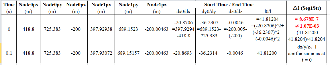
- For the “strain of each segment” output (marked “s”) in the outputs of the “LINES” section of the input file, my manually calculated value of −8.678E−7 differs substantially from the output value 1.07E−03 for Seg1Str from the MD.Line1 file at t = 0.1 s. The detailed calculation is shown in the table below.
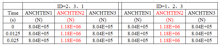
- For the “ID” field in the “LINES” section of the input file, manually setting the ID values has no effect — they are assigned internally by the system in sequential order (1, 2, 3, …). Furthermore, the subsequent outputs MD.Line# and AnchTen# correspond to these ID values. I modified the IDs here from the default 1, 2, 3 to 2, 3, 1, yet, strangely, the outputs both ANCHTEN1, ANCHTEN2, ANCHTEN3 and the MD.Line1 file results did not change accordingly. The specific outputs of ANCHTEN are shown in the table below.
- For the “LINE TYPES” section in that input file, MassDen should be 108.63 kg/m rather than 113.35 kg/m, according to the “Equivalent Mooring Line Mass in Water” in Table 5‑1 on page 26 of Definition of the Semisubmersible…. Based on the output Seg1SRt = −7.07E−06 1/s (marked “d”) from LINE1 at t = 0.1 s, I calculated Seg1Dmp = −86.32 N, which matches the output result (marked “c”) when MassDen = 113.35 kg/m according to page 9 of that manual, as detailed below. However, strictly speaking, this calculation is incorrect due to the erroneous MassDen value.
Best regards,
Hi @Yangyang.Li,
Hopefully I can be of some help. Below are answers to your questions:
-
It is not clear to me what your strain calculation formula is, but I believe you have errors. The strain in MoorDyn is calculated as the distance between two nodes divided by the line length minus 1 (See eqn3 in the original theory paper).
-
You are correct, in OpenFAST v3.5.3 the LineID’s in the input files were ignored and lines were just assigned sequentially. More recent versions of OpenFAST use these line numbers and check values are sequential so that the output channels match the ID numbers. In-general, you should always order the ID’s of your lines/points/rods/bodies sequentially. This will avoid confusion with output channels regardless of MoorDyn version.
-
MoorDyn takes the unsubmerged mass density as an input, not the submerged density. The geometry of the mooring line is then used to calculate the buoyancy forces. This is why the input is the true mass density and not the mass density in water.
Dear @Ryan.Davies ,
Thank you for your prompt assistance; however, I still have the following questions:
-
Regarding the “strain in MoorDyn,” I reproduced the calculation of Seg1Str (the first segment, output marked “s”) using Equation (3) from the reference you provided. However, the result remains the same: my Seg1Str = −8.678E−7 differs substantially from the output value 1.07E−03 reported in the MD.Line1 file at t = 0.1 s. In Equation (3), at this point i = 0; r1 and r0 represent the position vectors of the start node (anchor) and the first node, respectively, at t = 0.1 s. The original length l is calculated from the position vectors of the start node and the first node at t = 0 s. For convenience, the detailed calculation is provided in the Google Drive link below:
https://docs.google.com/spreadsheets/d/1rjyqiGl3BtVZEl0yoNIy-P-M8jOotUBx/edit?usp=sharing&ouid=100534356249426457824&rtpof=true&sd=true
-
MassDen is different from w (from the BA calculation formula on page 9 of the MoorDyn manual).
Best regards,