Interpreting LSSTipVxs and sectional velocities (N8RVXg) in OpenFAST

Hello everyone,

I have a couple of questions regarding the interpretation of simulation outputs in OpenFAST

Question 1:

  • LSSTipVxs (RotSpeed) represents the rotor azimuth angular speed in rpm.

  • N8RVXg represents sectional angular/rotational velocities (absolute) at Node 8 (say at 70% of blade length) in FAST’s global inertial frame, measured in deg/s.

If I convert both into rad/s, does the difference between RotSpeed and N8RVXg represent the in-plane speed deviation at Node 8?

or should I consider, TipRVXg -N8RVXg

Question 2:
Since N8RVXg is defined in the global inertial frame, does this value also include the effects of tower motion when reporting the blade’s sectional speed?

Thanks in advance.

Regards
Abhinay Goga

Dear @Abhinay.Goga,

Regarding (1), the difference between BeamDyn output N8RVXg and ElastoDyn output LSSTipVxs (RotSpeed) is that LSSTipVxs only includes the rotational speed of the rotor and is expressed about the shaft axis whereas N8RVXg (and similar BeamDyn rotational velocity outputs) includes all rotational speeds (including elastic motion of the tower and blades) and is expressed about the global X axis of the inertial frame.

Regarding (2), yes, both tower and blade elasticity is included in N8RVXg (and similar BeamDyn rotational velocity outputs).

Best regards,

1 Like

Dear Jason and all,

Like always, thank you for your timely and informative response.

My requirement is to accurately measure the in-plane blade oscillations of all blades, so that we can apply our flywheel model to reduce/damp these oscillations.

  1. Since BeamDyn outputs blade rotational speeds, which also include tower motions, I can obtain sectional speeds along the blade (N_RVXg) as well as tip speeds (TipRVXg). However, I do not see any output that provides the collective rotor rotational speed about the global X-axis of the inertial frame. Is there an output variable that would serve this purpose?

  2. From ElastoDyn, RotSpeed is given about the shaft axis. In addition, I found the tower-top linear velocity (NcIMUTVxs) expressed in m/s. By combining this with the azimuth angle of each individual blade (CosBl_), I can estimate the rotational speed influence of tower motion on each blade. Adding this to RotSpeed would then provide a reference rotational speed for each blade:

blade_motion_inplane_reference = RotSpeed + NcIMUTVxs * CosBl1;  
blade_motion_inplane_BeamDyn   = N_RVXg;   (at 70% blade span)  
blade_speed_difference = blade_motion_inplane_reference - blade_motion_inplane_BeamDyn;

Would this be a more appropriate approach, assuming BeamDyn does not provide a direct output for this quantity?

Thank you in advance.

Best Regards,
Abhinay Goga

Dear @Abhinay.Goga,

Your approach sounds OK, but is missing the affect of the local coordinate system each output uses, e.g,. with the shaft coordinate system (s) changing as the tower deflects.

I would suggest using the BeamDyn rotational velocity output at the root of the blade, e.g., N1RVXg where OutNd(1) = 1, which is the blade root that doesn’t have any blade elastic deflection.

Best regards,

1 Like

Dear Jason and all,

Thank you once again for your assistance. I have a follow-up question: For the three blades, N1RVXg is the same, correct? From a logical perspective, when the hub/rotor axis rotates at a particular angular speed, the adjoining blade nodes without spatial deflection should exhibit the same angular speed. This seems to be confirmed by my simulation results.

I also have another question, which is not directly related to the title of this thread but still relevant to the overall topic. I hope this is acceptable.

When the blades accelerate in the rotor rotational direction, charging the flywheel (FW) produces a Coriolis effect that slows down the rotational speed. Conversely, when the blades rotate more slowly compared to the center of rotation, discharging the fluid from outwards to inwards produces a Coriolis effect that accelerates the blades. These continuous charging and discharging cycles are applied to damp the in-plane blade oscillations.

What I am struggling with is the physical correlation: reducing the in-plane blade oscillations appears to reduce the tower fatigue loads in the fore-aft (wind) direction. I am unable to fully explain this link between the damping of in-plane blade oscillations and the resulting reduction in tower structural loads. Do you have any insights into this correlation?

Thanksin advance.

Regards,
Abhinay Goga

Dear @Abhinay.Goga,

If there is active independent pitch control, the blades may have different rotational velocity about the pitch axis, but otherwise I agree with your point about N1RVXg being the same for all blades when OutNd(1) = 1.

Can you clarify what you are seeing with regards to in-plane motion affecting tower fore-aft fatigue? I’m not sure I understand enough to comment.

Best regards,

Dear Jason and all,

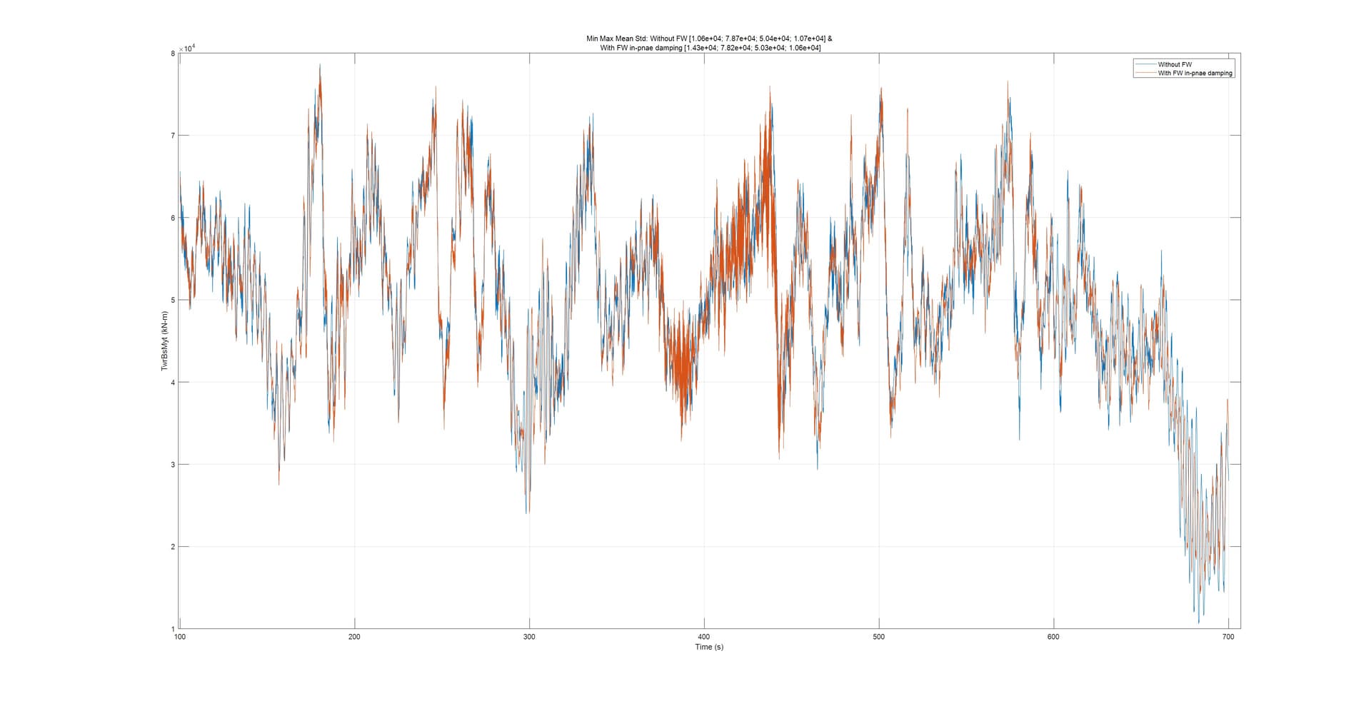
Let me walk you through my findings with the help of some plots, as they may provide insights into the issue at hand. Below you see results from a typical 600-second simulation of one DLC.

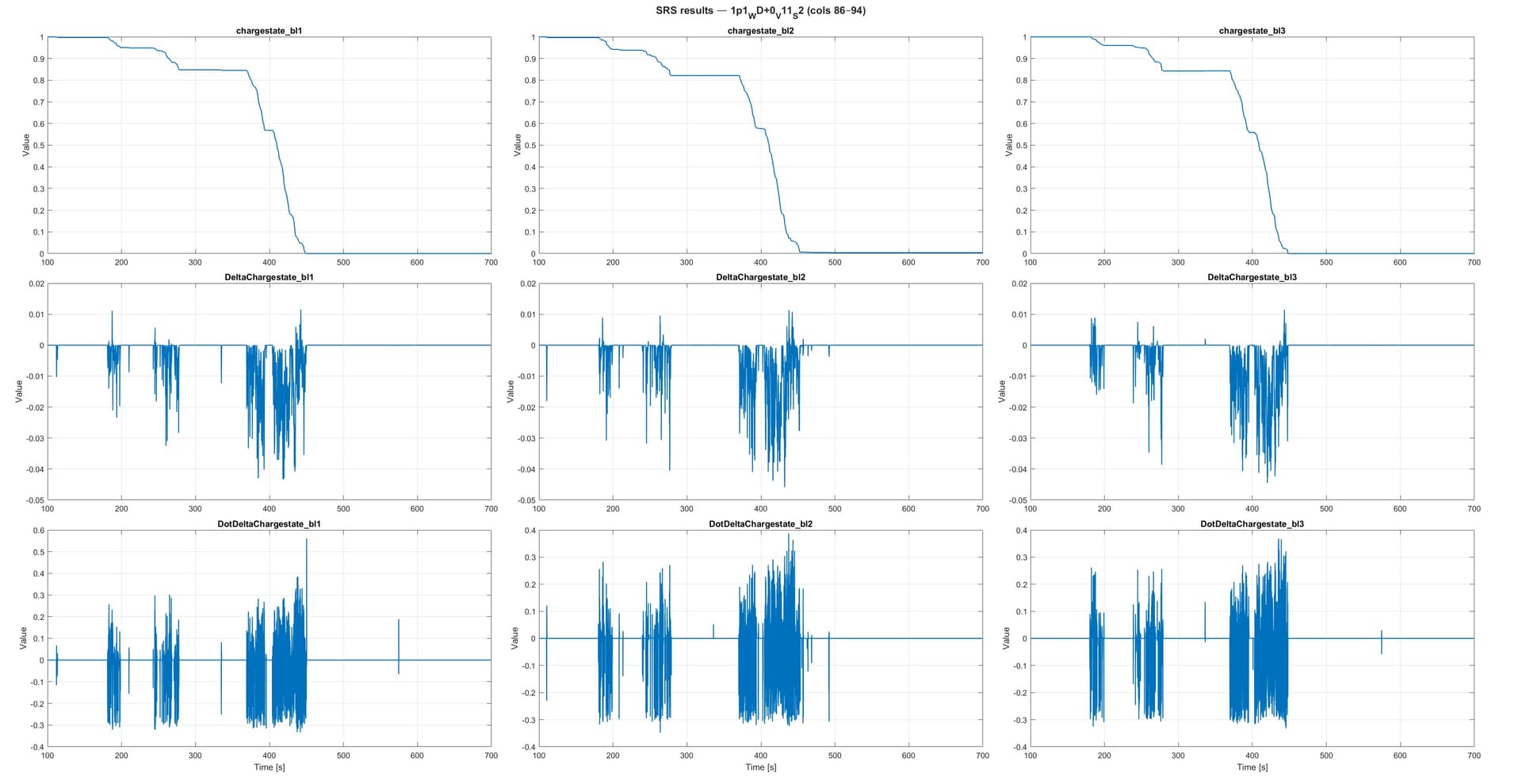
Initially, all blades are charged with the FW. By design, the FW discharges, and in some cases—depending on the available wind capacity—it also charges again. In this particular case, charging is rare due to the low wind regime.

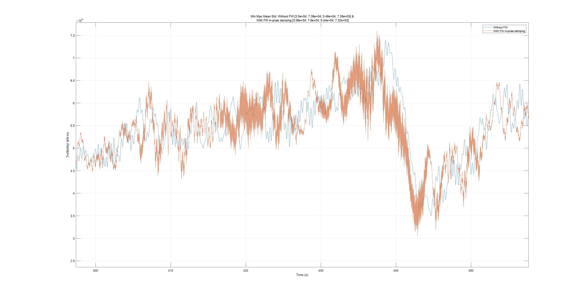
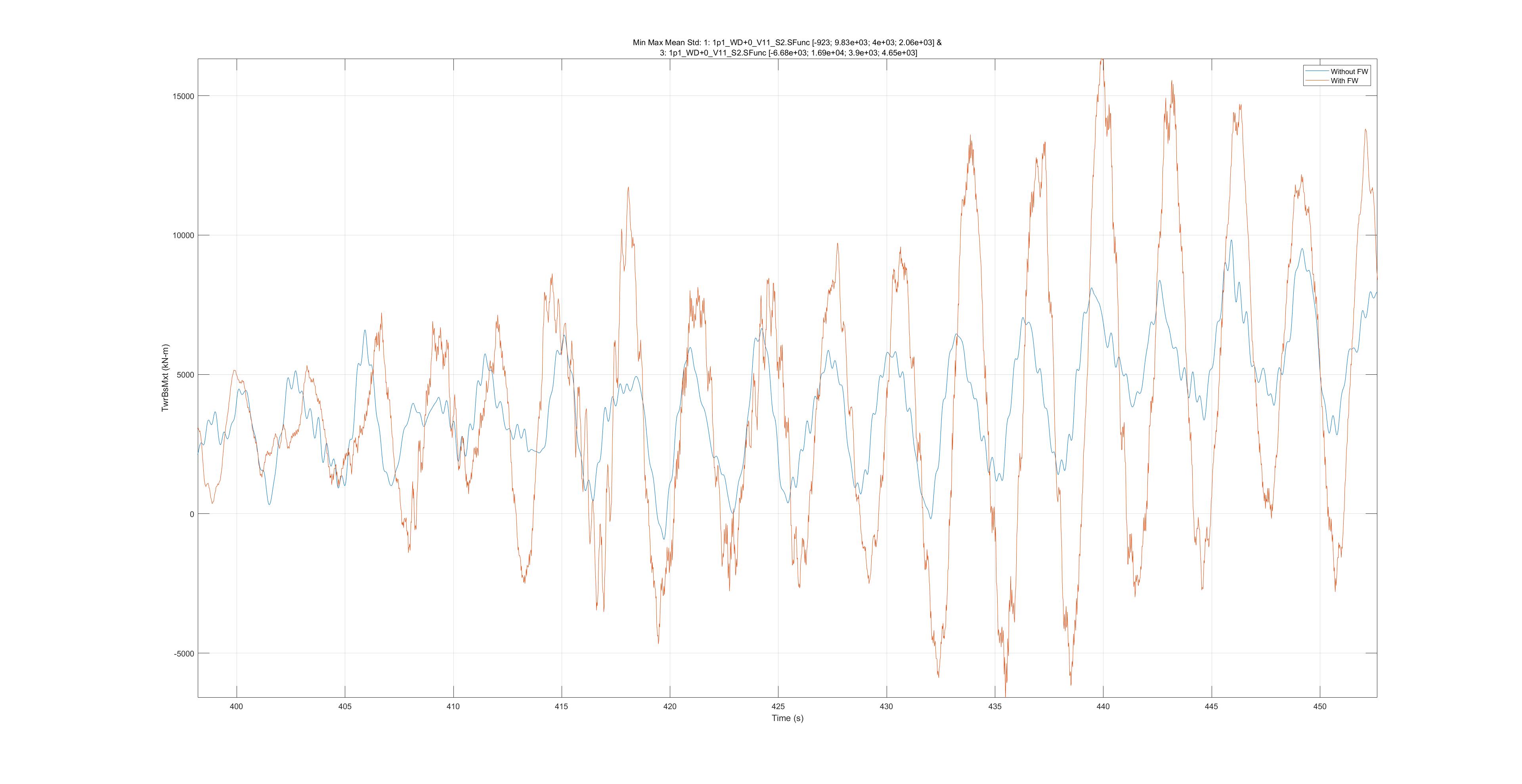
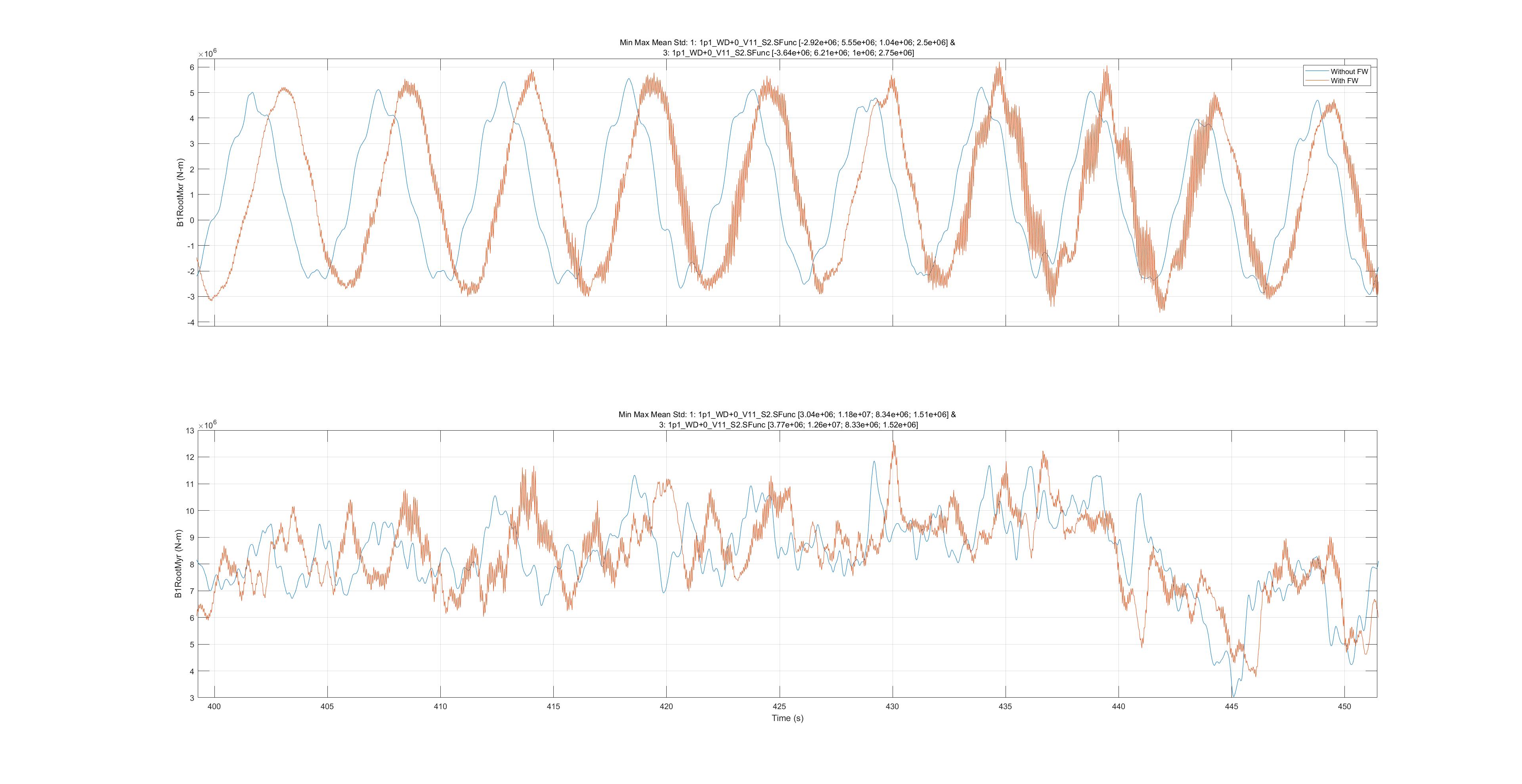
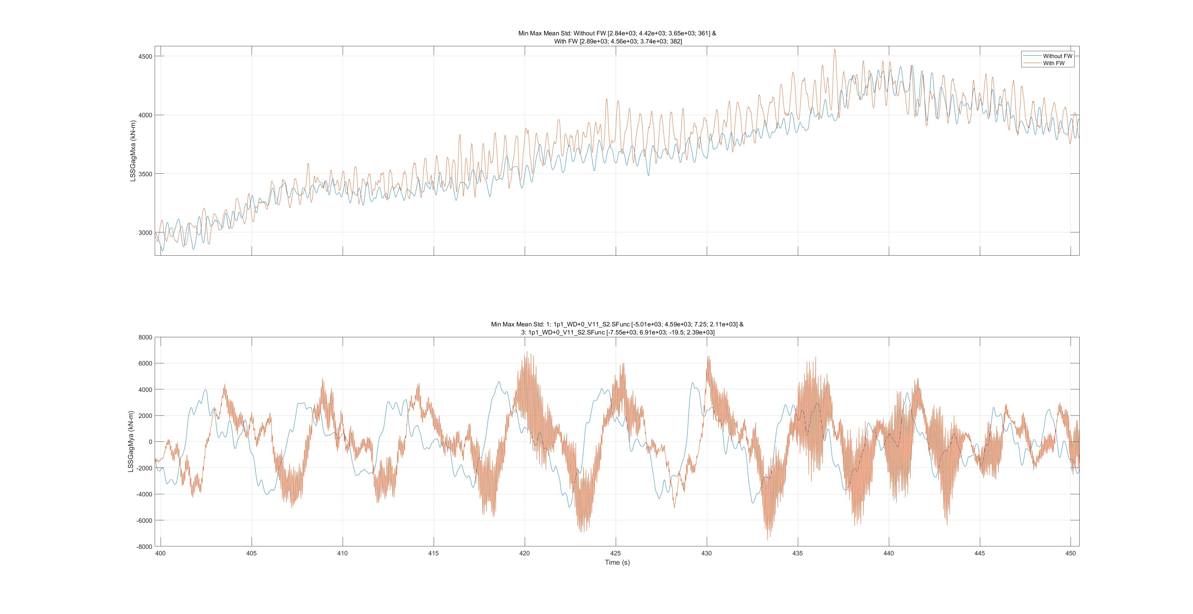
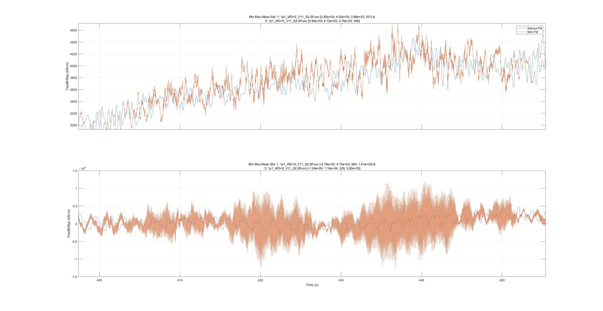
However, frequent discharge cycles are evident between 400 and 450 seconds. Therefore, in the following figures, I will focus on this specific region.

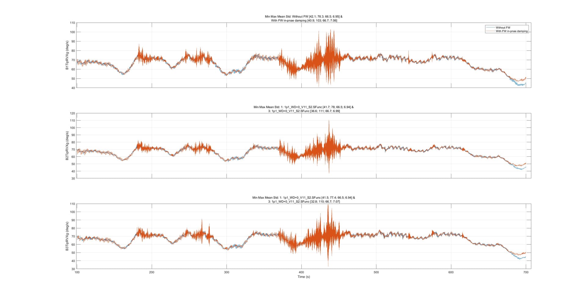
The individual blade in-plane speeds:

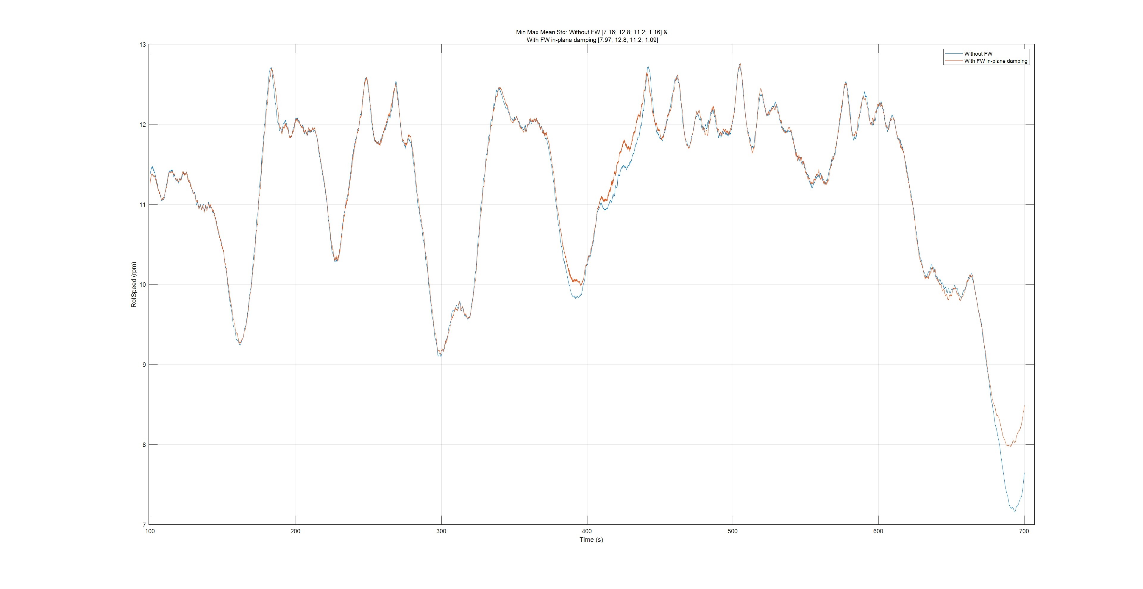
The collective rotor speed clearly shows a lower standard deviation.

Since the pitch angle between 400 and 420 seconds is zero, the observed increment in rotor speed can be attributed directly to the Coriolis effect of the FW.

Moving to the fore-aft bending moment, you can observe that both the mean value and the standard deviation are reduced when the FW is active.

To extend this finding, I performed the entire DLC 1.2 with NTM and calculated the fatigue loads. The following results summarize the fore-aft bending moment for different Wöhler slopes:

Wöhler slope: 3 4 5
without FW: 60627.42 54773.38 53195.35
With FW: 55050.74 49820.65 48681.21

Thus, not only in this single case but overall, the fatigue load in the fore-aft direction is consistently reduced due to the damping effect.

My main question is: why does damping the in-plane blade oscillations result in a reduction of the tower structural loads in the fore-aft direction? Any insights you can provide in connecting these effects would be greatly appreciated.

Best Regards
Abhinay Goga

Dear @Abhinay.Goga,

I’m a bit surprised the DEL is changing by about 10% when the std you are showing in your example only changes by about 1%. Perhaps your example is not representative of other cases?

What is happening with the blade-root flapwise moment, blade-root edgewise moment, and tower-base side-side moment stds/DELs?

Best regards,

Dear Jason and all,

The presented scenario is one of 216 simulations of DLC 1.2.

As requested, I have prepared plots for the aforementioned simulation time window.

TwrBsMxt (kN-m)
slope: 3 4 5
With out FW: 36116.88 32259.94 31037.41
With FW: 34834.38 32590.69 32565.99

B1RootMxr (N-m)
slope: 9 10 11
With out FW: 9.84E+06 9.65E+06 9.50E+06
With FW: 1.09E+07 1.07E+07 1.06E+07

B1RootMyr (N-m)
slope: 9 10 11
With out FW: 1.18E+07 1.21E+07 1.24E+07
With FW: 1.19E+07 1.22E+07 1.25E+07

Although the small load ranges at higher frequencies increase due to the FW damping action, if the FW reduces the peak magnitudes and the number of their occurrences, then the overall DEL will decrease. This is because the DEL, or accumulated damage, depends much more strongly on the load range raised to the power of the Wöhler slope than on the number of occurrences. I can also confirm this reduction in DEL from the generated rainflow matrix.

A direct comparison of blade loads is not entirely relevant here, since the blades without FW are lighter, while the blades with FW are heavier due to the integrated FW components.

By damping the blade oscillations, the rotor becomes more stable, and as a result the thrust deviations are reduced, which in turn affects the structural loads on the tower. Does my reasoning correctly explain the results?

Regards
Abhinay Goga

Sounds reasonable to me; thanks for clarifying.

1 Like

Dear Jason and all,

According to the OpenFAST documentation, the global coordinate system is defined as shown below.

From this definition, I assume that the edge-wise (in-plane) angular speeds of the blade sections should correspond to the Y-axis component (RVYg). However, based on my simulation results, the rotational speeds along different blade span positions appear to match more closely with the X-axis component (RVXg) at the hub.

1. Could you please confirm whether I am interpreting the coordinate system correctly?

As I move away from the root, I observe that the outputs at Node 6 (near 90% span) and the tip are increasingly influenced by vibrations, which I assume result from structural elasticity and deflections or torsional coupling from other axes.

  1. Would it be reasonable to calculate the in-plane angular speed difference by taking the difference between Root (B1N1RVXg) and Tip (TipRVXg) values?

3. For my Flywheel (FW) application, would it therefore be more appropriate to use a weighted average of these angular speeds (Node 6 and Tip) to estimate the in-plane angular speed difference between the hub and the cantilever end of the blade?

Any insights or clarification would be greatly appreciated.

Best regards,
Abhinay Goga

Dear @Abhinay.Goga,

Regarding (1), I’m not sure why you say rotor rotation should be about the Y axis. The rotor rotation should be about the X axis according to that figure, which matches the time-series results you are sharing.

Regarding (2), By “angular speed difference”, I assume you mean the rotational velocity associated purely with elastic motion (separate from rigid-body rotor rotation). If so, I agree with your interpretation.

Regarding (3), I agree that weight-averaging between different radial stations could be used to get the rotational velocity closer to the station where the flywheel will be installed

Best regards,

1 Like