IEA 15 MW RWT: fixed foundations. Discrepancy in RtAeroPwr among OLAF and BEMT

Dear all,

I’m working on the IEA 15 MW RWT to develop my MSc thesis.
At the moment I’m trying to validate the results I obtained with BEMT with a higher fidelity method (OLAF).
For this reason I am currently trying tosimulate the wind turbine with fixed foundations. The wind turbine is modelled as rigid. SubDyn, HydrDyn, ServoDyn and MoorDyn modules are not activated. The wind is uniform and steady, with constant rated value (10.59 m/s).

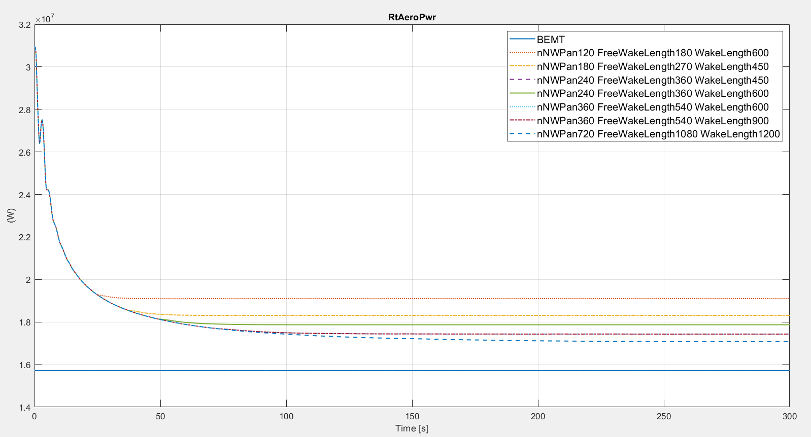
My concern arises since the RtAeroPwrs that I obtain with OLAF and BEMT differ significantly. In particular, the RtAeroPwr for OLAF is also way higher than rated power.

For OLAF input file, initially I tried following the recommendations on the OpenFAST online documentation. After that I tried modifying the DeltaPsi parameter (suggested as 6° in the documentation) and all the parameters which, according to the documentation, can be defined from it (i.e. DTfvw, nNWPanel, WakeLength, FreeWakeLength). I could not achieve a result closer to BEMT anyway.

Afterwards I tried modifying nNWPanels, FreeWakeLength and WakeLenght parameters, leaving DTfvw untouched: the idea is to increase the near wake region. I could reach steady values closer to BEMT one, but still with more than 8% difference.
I’m attaching a plot where different simulations are compared over time (with Power on the y-axis). It shows BEMT compared with many different OLAF simulations (differences in setting are written in the legend). The recommended values would be nNWPanel=120; FreeWakeLenght=180; WakeLength=600, and are the ones leading to the red dotted line (the farthest from BEMT value).

I was wondering if you knew why the results are so different – or if you could advise on how to achieve a better match.

Thank you very much,
Best regards,
Riccardo

Hi Riccardo,

Thank you for trying this out, and spending your time and computational time investigating this.

We’ve observed similar results with OLAF, the Cp coefficient being higher than BEM. Typically, a longer near wake indeed improves the results.

I unfortunately cannot pinpoint an issue at the moment, comparisons between OLAF and other vortex codes typically show good agreements, so it might be something about segment-based vortex methods.

If you have the time, here are some suggestions on what else you can try:

  • You can plot the axial and tangential inductions along the blade span, that can give an idea of where the differences are.
  • The regularization factor might have a significant impact on the results. You can adjust the WingRegFactor (likely reducing it). You might also find that adjusting the WakeRegFactor has an influence on the results. If you reduce WakeRegFactor, you might want to increase the CoreSpreadEddyVisc a bit.
  • You can use WakeRegMethod=2 (proportional to chord instead of span), but that will change the distribution of axial induction quite a lot, and you’ll therefore have to tune WingRegFactor and WakeRegFactor again.
  • A bit of a shot in the dark, but you can try using VelocityMethod=4 (Segment Tree instead of Particle-Tree). It should be more precise, for not too much computational time overhead. The issue is that then the code uses segments, and the regularization factor for segments and particles might be slightly different, meaning that you will likely need to re-tune these values…
  • You can try to use a slightly different algorithm (more similar to the one used by the vortex code CACTUS). The options are “hidden”. At the end of OLAF input file, you can add the following lines:
------------------- ADVANCED OPTIONS ----------------------------------------------------------
False         InductionAtCP - Compute induction at the Control Points or at the lifting line nodes
False         WakeAtTE        -  Start the wake at the Trailing Edge, or at the lifting line.

Last time I modeled the IEA 15 MW, these are the parameters I used:

0.18    DTfvw              Time interval for wake propagation. {default: dtaero} (s)
420     nNWPanel           Number of near-wake panels [integer] (-)
120     FarWakeLength      Total wake distance [integer] (number of time steps)
60      FreeFarWakeLength  Wake length that is free [integer] (number of time steps) {default: WakeLength}
default FWShedVorticity    Include shed vorticity in the far wake {default: false}
------------------- WAKE REGULARIZATIONS AND DIFFUSION -----------------------------------------
0       DiffusionMethod    Diffusion method to account for viscous effects {0: None, 1: Core Spreading, "default": 0}
3       RegDeterMethod     Method to determine the regularization parameters {0: Manual, 1: Optimized, 2: Chord, 3: Span, default: 0 }
3       RegFunction        Viscous diffusion function {0: None, 1: Rankine, 2: LambOseen, 3: Vatistas, 4: Denominator, "default": 3} (switch)
3       WakeRegMethod      Wake regularization method {1: Constant, 2: Stretching, 3: Age, default: 1} (switch)
0.5     WakeRegFactor      Wake regularization factor (m)
0.25    WingRegFactor      Wing regularization factor (m)
2000    CoreSpreadEddyVisc Eddy viscosity in core spreading methods, typical values 1-1000

But I should say that I didn’t compare the results with other codes, so it might need further tuning.

Hopefully, by just adjusting the RegFactors you’ll get a bit closer. But you might stay within the same range of error.

If you don’t mind, please let us know the conclusions of your study.

Thanks a lot, and sorry for the potential frustrations.

Emmanuel

Hi Emmanuel.
Thank you for the quick answer: I took my time to reply back in order to have some meaningfull results to discuss.

I decided to stick to WakeRegMode=3 (age method) since I already had some experience with it. I realized that also turning to RegFunction=3 (Vatistas, instead of 2=LambOseen) can be helpful - even though marginally.
What really made the difference was reducing WakeRegFactor (in my case, from 0.6 to 0.4) and increasing BladeRegFactor (from 0.6 to 0.8). With these new settings I could also reduce a bit the nNWPanel, thus reducing computational time.

Regarding changing Velocity method, I already tried and it did not change results, so I don’t think it helps much.

Here below a couple of charts to justify my words, and the relevant details of the OLAF.dat file. The setting could possibly be improved a little more to reduce the fluctuations you can see on the second chart.

5       IntMethod          Integration method {1: Runge-Kutta 4th order, 5: Forward Euler 1st order, default: 5} (switch)
--------------------------- CIRCULATION SPECIFICATIONS ----------------------------------------
1       CircSolvingMethod  Circulation solving method {1: Cl-Based, 2: No-Flow Through, 3: Prescribed, default: 1 }(switch)
===============================================================================================
--------------------------- WAKE OPTIONS ------------------------------------------------------
------------------- WAKE EXTENT AND DISCRETIZATION --------------------------------------------
420     nNWPanel           Number of near-wake panels [integer] (-)
600     WakeLength         Total wake distance [integer] (number of time steps)
200     FreeWakeLength     Wake length that is free [integer] (number of time steps) {default: WakeLength}
False   FWShedVorticity    Include shed vorticity in the far wake {default: false}
------------------- WAKE REGULARIZATIONS AND DIFFUSION -----------------------------------------
0       DiffusionMethod    Diffusion method to account for viscous effects {0: None, 1: Core Spreading, "default": 0}
3       RegDeterMethod     Method to determine the regularization parameters {0: Constant, 1: Optimized, 2: Chord-scaled, 3: dr-scaled, default: 0 }
3       RegFunction        Viscous diffusion function {0: None, 1: Rankine, 2: LambOseen, 3: Vatistas, 4: Denominator, "default": 3} (switch)
3       WakeRegMethod      Wake regularization method {1: Constant, 2: Stretching, 3: Age, default: 1} (switch)
0.4     WakeRegFactor      Wake regularization factor (m or -)
0.8     BladeRegFactor     Blade regularization factor (m or -)
1000    CoreSpreadEddyVisc Eddy viscosity in core spreading methods, typical values 1-1000

Best regards,
Riccardo

Hi Ricardo,

Thanks a lot for taking the time to try all this and sharing these values.

  • Can you maybe add to your post (above the input values for instance) the operating conditions: Wind Speed (10.19m/s), Rotational Speed, Thrust coefficient, Tipspeed ratio, Time step used for OLAF ( 6deg).
  • Let us know if you find that these parameters need to change with the thrust coefficient.
  • I’m guessing you managed to capture the power well, but likely the thrust is slightly off. It’s usually hard to get both, no?
  • Increasing CoreSpreadEddyVisc might reduce some of the oscillations you observe.

Thanks again for all your tries. Keep us updated,

Emmanuel

Hi Emmanuel,

The conditions used are rated ones:

  • TSR: 9.0 [-]
--------------------------- INITIAL CONDITIONS AND RELEVANT SETTINGS: INPUT FILE -----------------
****InflowFile.dat
================== Parameters for Steady Wind Conditions [used only for WindType = 1] =========================
10.59                  HWindSpeed  - Horizontal windspeed                            (m/s)
135.0                  RefHt       - Reference height for horizontal wind speed      (m)
0.00                   PLexp       - Power law exponent                              (-)

*****ElastoDyn.dat
---------------------- DEGREES OF FREEDOM --------------------------------------
False                  FlapDOF1    - First flapwise blade mode DOF (flag)
False                  FlapDOF2    - Second flapwise blade mode DOF (flag)
False                  EdgeDOF     - First edgewise blade mode DOF (flag)
False                  TeetDOF     - Rotor-teeter DOF (flag) [unused for 3 blades]
False                  DrTrDOF     - Drivetrain rotational-flexibility DOF (flag)
False                  GenDOF      - Generator DOF (flag)
False                  YawDOF      - Yaw DOF (flag)
False                  TwFADOF1    - First fore-aft tower bending-mode DOF (flag)
False                  TwFADOF2    - Second fore-aft tower bending-mode DOF (flag)
False                  TwSSDOF1    - First side-to-side tower bending-mode DOF (flag)
False                  TwSSDOF2    - Second side-to-side tower bending-mode DOF (flag)
False                  PtfmSgDOF   - Platform horizontal surge translation DOF (flag)
False                  PtfmSwDOF   - Platform horizontal sway translation DOF (flag)
False                  PtfmHvDOF   - Platform vertical heave translation DOF (flag)
False                  PtfmRDOF    - Platform roll tilt rotation DOF (flag)
False                  PtfmPDOF    - Platform pitch tilt rotation DOF (flag)
False                  PtfmYDOF    - Platform yaw rotation DOF (flag)

7.56                   RotSpeed    - Initial or fixed rotor speed (rpm)
-0.51                  PtfmHeave   - Initial or fixed vertical heave translational displacement of platform (meters)
0.18                   PtfmRoll    - Initial or fixed roll tilt rotational displacement of platform (degrees)
4.17                   PtfmPitch   - Initial or fixed pitch tilt rotational displacement of platform (degrees)
0.026                  PtfmYaw     - Initial or fixed yaw rotational displacement of platform (degrees)

****----------------------- OLAF (cOnvecting LAgrangian Filaments) INPUT FILE -----------------
5       IntMethod          Integration method {1: Runge-Kutta 4th order, 5: Forward Euler 1st order, default: 5} (switch)
0.132   DTfvw              Time interval for wake propagation. {default: dtaero} (s)
--------------------------- CIRCULATION SPECIFICATIONS ----------------------------------------
1       CircSolvingMethod  Circulation solving method {1: Cl-Based, 2: No-Flow Through, 3: Prescribed, default: 1 }(switch)
--------------------------- WAKE OPTIONS ------------------------------------------------------
------------------- WAKE EXTENT AND DISCRETIZATION --------------------------------------------
420     nNWPanel           Number of near-wake panels [integer] (-)
600     WakeLength         Total wake distance [integer] (number of time steps)
200     FreeWakeLength     Wake length that is free [integer] (number of time steps) {default: WakeLength}
False   FWShedVorticity    Include shed vorticity in the far wake {default: false}
------------------- WAKE REGULARIZATIONS AND DIFFUSION -----------------------------------------
0       DiffusionMethod    Diffusion method to account for viscous effects {0: None, 1: Core Spreading, "default": 0}         
3       RegDeterMethod     Method to determine the regularization parameters {0: Constant, 1: Optimized, 2: Chord-scaled, 3: dr-scaled, default: 0 }          
3       RegFunction        Viscous diffusion function {0: None, 1: Rankine, 2: LambOseen, 3: Vatistas, 4: Denominator, "default": 3} (switch)
3       WakeRegMethod      Wake regularization method {1: Constant, 2: Stretching, 3: Age, default: 1} (switch)
0.4     WakeRegFactor      Wake regularization factor (m or -)
0.8     BladeRegFactor     Blade regularization factor (m or -)
1000    CoreSpreadEddyVisc Eddy viscosity in core spreading methods, typical values 1-1000 

Here a prospect of Rotor Power, Thrust and Torque. Although thrust is slighty off, it’s only 0.4%, so still a quite acceptable results.

I observed increasing CoreSpreadEddyVisc did not help, that’s why I did not change it.

Thank you again,
Best regards,
Riccardo

Thanks a lot for taking the time to answer!

Hi @Riccardo.Ramponi @Emmanuel.Branlard thank you for your nice discussions.

Indeed, I encountered the same problem when simulating NREL5MW with OpenFAST, the RtAeroPwrs predicted by OLAF (nNWPanel=120, FreeWakeLength=180, WakeLength = 600) is slightly higher than the results of BEMT, moreover, their difference becomes much evident if yaw misalignment presents, the same results were also observed in the work of Shaler et al. 2022 when studying BAR wind turbine.
(Shaler et al. Comparison of Free Vortex Wake and BEM Structural Results Against Large Eddy Simulations Results for Highly Flexible Turbines Under Challenging Inflow Conditions. Wind Energy Science. 2022)

In this discussion, I understand you were trying to adjust OLAF parameters to approach the rated power, which is well captured by BEMT method at rated inflow (10.59 m/s). However, these adjusted discretisation and regularization parameters may be still questionable when applying them in other operating conditions (different inflow velocities, yaw …). Did you try other conditions and compare against experimental results in your work?

Looking forward to reading your thesis work someday.
Best regards,
Wenchao

Hi @Wenchao.Yu,

thank you for sharing previous results than can help me understanding better the topic.
I had already checked the setup with above rated conditions (WindSpeed=16 m/s) and the models were still in good agreement, yet not as precise as for rated.

Percentage difference:

  • Power: 0.25%
  • Torque: 0.25%
  • Thrust: 0.35%

In the near future I’ll be validating below rated conditions (WindSpeed=5 m/s), as soon as I have results I’ll be sharing here. I don’t plan to introduce yaw misalignment, but I’d be happy to share everything you need in case you want to study that condition: OLAF parameters should already be up here, still don’t hesitate asking if you have doubts.
Finally, no experimental results were compared so far.

Best regards,
Riccardo

Thank you both for your work and comments.

For (my own) reference, I’m writing down the parameters given by Riccardo for IEA 15MW, trying to give dimensionless values whenever possible:

  • TSR=9 (U0=10.59 m/s, Omega=7.56 rpm, R=117 m)
  • CT=0.8, CP=
  • dpsi = 6 Omega dt = 6 deg, (delta t=0.132 s)
  • nNWPanel = 420 = 7 rotations (2520 deg)
  • nFWpanel = 600 = 10 rotations (3600 deg) (also called “WakeLength”)
  • nFWPanelsFree = 200 = 3.3 rotations (1200 deg)
  • RegDeterMethod =3 (i.e. based on dr , with dr = 0.02 R
  • RegFunction =3
  • WakeRegMethod=3
  • WakeRegFactor=0.4 (dr, with dr = 0.02 R)
  • BladeRegFactor =0.8 (dr, with dr = 0.02 R)
  • CoreSpreadEddyVisc=1000

Ideally, the wake extents in terms of downstream distance would be used, but this information is hard to use. For different operating conditions, the CT and the axial induction change, which affects the distance convected by the wake. In theory, we should try and keep the convected distance (of the near wake and far wake) more or less the same across operating conditions. Therefore the n*Panels might need to change slightly with operating conditions.

I would hope that the regularization parameters do not need to change. The rated conditions are usually the ones with fairly large CT (therefore with large wake extension and slow wake convections), they are usually the most challenging ones to simulate.

Dear Emmanuel,

My question is not related to the issue that is discussed here, but rather stems from the fact that you suggested to compare induction factors between BEM and LLFVW.

I am wondering, how is the induction factor that is outputted by AeroDyn computed along the blade span in LLFVW? I know it is a result of the momentum balance in BEM, but I could not find any info on this in the OLAF manual for LLFVW.

Thank you in advance,

Francesco Papi

Dear Francesco,

The induced velocity computed by OLAF is computed on the lifting-line nodes using the Biot-Savart law, once all the intensity of the vortex filaments are known (i.e. after solving for the circulation on the blade and shedding/trailing it in the wake).
The induced velocity at a node is a vector (expressed in global coordinates). This vectors is projected onto the same coordinate system as the one used by OpenFAST for BEM, projected into an axial and tangential component in this system, and made dimensionless using the same velocities as used in BEM (more or less U0 and omega r) to get the axial and tangential induction factors. The same is true for all the other outputs of AeroDyn: their definitions are consistent between BEM and OLAF.

Concerning the momentum balance, in theory, vorticity-based formulations and momentum-formulations should return the same results. The BEM method, though, rely on some assumptions (independence of annuli, rigid wake, actuator disc) which are not present in the vortex wake method.

I hope that helps,

Emmanuel