Dear Jason,
Another question came up: I am trying to output the fairlead tension. I am using MAP++. At the last 6 columns of the silumation’s primary.out file the legends are T[1], T_a[1], T[2], T_a[2], T[3], T_a[3], all of them measured in Newtons. Are these the fairled tension and if yes, what is the difference between T and T_a?
If these are not the fairlead tension components, then should I work with the MAP++ properties as described in Input File — MAP++ 1.15 documentation ?
For your convenience, I am sharing with you the MAP++ that I already used.
Thank you once more in advance!
Best Regards,
Nikos
Dear @Nikos.Mantadakis,
In MAP++, T[n] is the tension at the n’th fairlead and T_a[n] is the tension at the n’th anchor.
Best regards,
Dear Jason,
Thank you once again for your prompt reply!
Best Regards,
Nikos
Dear @Jason.Jonkman
I am studying the “FAST Kinematics” file in the ElastoDyn Users Guide and Theory Manual for OpenFAST: 4.9. ElastoDyn Users Guide and Theory Manual — OpenFAST v4.0.2 documentation. During my study, I encountered the following questions and made some interpretations. Are they correct? The meanings of the letters in the formulas I provided are consistent with those in the document.
- The linear acceleration term on page 19 of that document, specifically
- The linear acceleration term on page 18 of that document, specifically
- The angular acceleration term on page 16 of that document, specifically
- One letter error is located on page 18 of that file, as follows
Best regards,
Dear @Jason.Jonkman ,
Thank you for your prompt reply. I acknowledge that I overlooked the factor for r=FTA1 in my initial equation regarding Question 1. Consequently, I have revised the equations as follows. Are they correct?
Best regards,
Dear @Yangyang.Li,
I agree with these equations for r = 4, 5, 6, TFA1, and Yaw. However, you are missing the terms for r = 8 (TSS1), 9 (TFA2), and 10 (TSS2).
Best regards,
Dear @Jason.Jonkman ,
Thank you for your careful and responsible reminder. I would like to use r = TFA as an example to demonstrate that my idea is correct here.
Best regards,
Dear @Jason.Jonkman ,
I am studying the “FAST Kinetics” file in the ElastoDyn Users Guide and Theory Manual for OpenFAST: 4.9. ElastoDyn Users Guide and Theory Manual — OpenFAST v4.0.2 documentation, During my study, I encountered the following questions and made some interpretations. Are they correct?
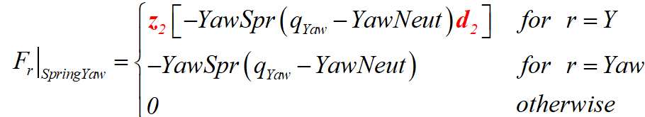
- The generalized active force caused by the yaw moment does not account for the partial angular velocity. The modification is as follows (on page 10 of that file).The meanings of the letters in the formulas I provided are consistent with those in the document.
- The calculation formula for “aerodynamic pitching moments caused by an aerodynamic offset” is as follows (Equation in line 3 on page 26 of that file). The symbol descriptions for BlSwpAC, BlCrvAC, and BαNβFx, BαNβFy can be found in Section 4.5 and Appendix E of the “AeroDyn v15 User’s Guide and Theory Manual” file.
Best regards,
Dear @Yangyang.Li,
Regarding (1), I would agree with your change to F_r|_SpringYaw if you add a dot product, but because E_omega_r^N = d_2 for r = Yaw, E_omega_r^N dot d_2 = 1 and your equation (with a dot product) is exactly the same as what is stated in the document.
Regarding (2), I agree that the aerodynamic pitch moment caused by an aerodynamic offset would be zero if BlSwpAC = BlCrvAC = 0, but I don’t agree with your calculation, e.g., because the x/y coordinate system where forces are output does not pitch with the blade whereas BlSwpAC/BlCrvAC do pitch with the blade and your equation is missing a vector direction because M^M1_AeroB1 is a vector. Also, at the end of the day, OpenFAST will use its spatial mesh-to-mesh mapping routines rather than an explicit equation you are trying to write to compute the pitch moment associated with the aerodynamic offset.
Best regards,
Dear @Jason.Jonkman ,
Thank you for your prompt responses. However, I still have some questions as follows:
Regarding (1), the partial angular velocity of the nacelle is also affected by those of the platform and tower displacement , in addition to its own partial angular velocity. For simplicity, assuming only r = (Y , Yaw) have partial angular velocities values (with other degrees of freedom disabled), the following conclusions can be drawn. However, this conclusion is inconsistent with the fact that the generalized active force of the nacelle in that document is zero for all components except r = Yaw.
Regarding (2), assuming the blade pitch is not considered and only the numerical magnitude of the additional aerodynamic moment is calculated, is the formula I proposed earlier correct?
Best regards,
Dear @Yangyang.Li,
I’m not really understanding your arguments.
For (1), the generalized active forces are tied to partial velocities of a specific DOF. The yaw spring is only tied to r=Yaw, not r=Y, given that the motion of the Yaw DOF is relative to the motion of the Y DOF. So, F_r|_SpringYaw is zero for all DOFs except r=Yaw.
For (2), I would say your image is not correct, because the “y” axis of the airfoil should point nominally to the trailing edge and I’m not sure about the signs of BlCrvAC and BlSwpAC, which should be positive along “x” and “y” axes, respectively.
Best regards,
Dear @Jason.Jonkman ,
I sincerely apologize for the lack of clarity in my question, and I truly appreciate your help. However, regarding (2), I still have the following doubts:
After flipping the y-axis to point toward the blade trailing edge, the values of BlSwpAC, BlCrvAC, BαNβFx, and BαNβFy are all positive in the coordinate system shown in the following figure. Under this condition, is the formula for the additional aerodynamic bending moment in the figure correct if only the magnitude is considered and yaw is ignored?
PS: The original coordinate system is established based on the footnotes in Appendix E of AeroDyn manual.
Best regards,
Dear @Yangyang.Li,
I’m still not understanding your figure. BlCrvAC and BlSwpAC should be defined from the pitch axis to the aerodynamic center, but you are showing the opposite (at least in terms of the arrow directions. Or does your figure show BlCrvAC and BlSwpAC as both negative in value? Also, you refer to yaw, but do you mean pitch?
Best regards,
Dear @Jason.Jonkman ,
Thank you for your prompt responses. The following analysis still ignores blade pitch, and please excuse my previous mistake of writing yaw instead.
Under your guidance, I have changed the directions of BlSwpAC and BlCrvAC to point from the pitch axis to the aerodynamic center. This time, I analyze the additional aerodynamic moment using vector analysis. The directions of BlSwpAC, BlCrvAC, BαNβFx, and BαNβFy should follow the schematic shown in the figure (if their directions conflict with those inside OpenFAST, the figure takes precedence). In the figure, is the calculation of the additional aerodynamic moment correct? The vectors i and j represent the unit orthogonal basis vectors of a coordinate system.
Best regards,
Dear @Yangyang.Li,
I agree with your math, but I still disagree with your figure. The arrows for BlCrvAC and BlSwpAC should be positive along the x (i) and y (j) directions and point towards the AC, meaning their starting point should be to the right and below the AC in your figure. Indeed, if a blade has sizeable BlCrvAC and BlSwpAC, the pitch axis does not need to pass through the airfoil cross section.
Best regards
Dear @Jason.Jonkman ,
Thank you for your prompt responses. Yes, I agree with your viewpoint on the signs of BlSwpAC and BlCrvA. While reading the ElastoDyn files :https://openfast.readthedocs.io/en/main/source/user/elastodyn/index.html, I have still some questions as follows and am unsure whether they are correct:
- Since the rotor rotates with wind, the torque at the hub, RotTorq, must be influenced by its acceleration or deceleration. However, in the calculation formula for RotTorq, the influence of the rotor’s moment of inertia is not considered—only the hub’s moment of inertia, I^H , appears. The specific formula is shown in Q1 in the figure below, located on page 14, line 4 of the “FAST Loads” document.
- LSShftFya and LSShftFza should be corrected as shown in Q2 in the figure below, located on page 14 of the “FAST Loads” document.
- The origin of the inertial coordinate system is located at the platform reference point, as indicated by the first equation on page 1 of the “FAST Kinematics” document. Therefore, the equation in the second line below should be corrected as shown in Q3 in the figure.
- DrTr DOF refers to the rotation between the hub center of mass and the apex of coning angle for a 3-bladed wind turbine without rotor-furl motion.
- The parameters NcIMUxn, NcIMUyn, NcIMUzn, and ShftGagL are only used for the output of loads and motions, but they are not involved in the formulation of equations of motion based on kinetics theory.
- The electrical generator torque, GenTq, comes from the power control results of the ServoDyn module, and the ElastoDyn module does not have relevant control parameters.
Best regards,
Dear Jason,
Hope you are doing well!
I have another question regarding OpenFAST simulations. I tried to run a simulation of the initial code (without my modifications) concerning a TurbSim wind profile having speed of 11.4 m/sec at the hub height. Since this is the rated speed for the 5 MW turbine, shouldn’t the average generated power (GenPwr) be around 5 MW? I am asking this because the average values that I compute is around 4.4 MW. Is this rational or am I doing something wrong? Maybe 11.4 m/sec is a threshold and should I consider a wind profile with a larger speed at hub height?
If you need to check any file that I use, please let me know.
Thak you very much in advance.
Best Regards,
Nikos
Dear @Nikos.Mantadakis,
If you are simulating with turbulent wind at rated wind speed, I would expect a bit less than rated power because power will be lost during the lulls and power will not exceed rated power (by much) during gusts.
Best regards,