Hi Jason
I increased the precision as suggested in below rated case, but the unstable poles are still there. There are unstable underdamped poles with damping for example -6.25e-02, -3.00e-04 etc.
Even after removing
- Generator Azimuth State
- Platform roll DOF,
there are a lot of unstable poles (both real and real + imaginary poles. I couldnt figure out how to resolve this issue!!
I have another query. How to check for mooring stiffness as I couldnt found any tab for Mooring variables in OutlistParameters.xlsx file.
Can you kindly suggest any debugging scheme to sort out the unstable poles, s.
Thanks
Dear @Muhammad.Sharjil,
I’m not sure I fully understand what you are saying. Are you saying that you removed the generator azimuth state and disabled the platform-roll degree of freedom (DOF) and unstable poles still remain?
I would suggest simplifying the model to better understand what is going on. Do you get unstable poles if the generator and all platform DOFs are disabled? Do you get instabilities in certain platform DOFs if you enable one at a time?
I now see that you have MoorDyn enabled (CompMooring = 3), although I don’t see MooDyn states in your linear model. Can you confirm? It may be easier to switch to MAP++ when linearizing to avoid having modes associated with the mooring line flexibility appearing in your linearized system.
Outputs associated with MAP++ or MoorDyn are discussed in their respective documentation:
https://moordyn.readthedocs.io/en/latest/inputs.html
https://map-plus-plus.readthedocs.io/en/latest/index.html
Best regards,
Hi @Jason.Jonkman
I tried multiple things but the unstable poles were quite good in number.
The first thing tried:
While running fst file, all DOF were ON
I excluded the GenDOF while making linear statespace model from postproLin_OneOP.m , AvgA, AvgB, AvgC, AvgD.
But I still got unstable poles (a lot of them with -1 damping, and also with damping less than -1)
Another thing I tried was to disable the platform DOF (sway, surge, heave, platform -roll, pitch, yaw). The resulting statespace linear model from AvgA, AvgB, AvgC , AvgD matrices was stable.
Regarding your suggestion
“… I now see that you have MoorDyn enabled (CompMooring = 3), although I don’t see MooDyn states in your linear model. Can you confirm? It may be easier to switch to MAP++ when linearizing to avoid having modes associated with the mooring line flexibility appearing in your linearized system.”
I was using the default setting of the file. Thanks for highlighting, I will try Map++ instead of Moordyn.
Thanks
Dear @Muhammad.Sharjil,
If the unstable poles dissappear after disabling the ElastoDyn platform DOFs, you should be able to isolate which DOFs are triggering the unstables poles (e.g., by running separate simulations for each platform DOF).
Best regards,
Hi @Jason.Jonkman
Using CompMooring = 1, solved the instability issue.
The poles are stable. The states are only 42 now.
Thanks for the response and highlighting the prime source of instability. 
1 Like
Hi @Jason.Jonkman
I am facing a strange issue
I am trying to linearize 15MW FOWT at
- Wind = 10m/sec, RPM = 5
I am using these settings
TrimTol = 0.01,
Trimcase = 2.
The simulation is completing without errors, but instead of linearizing at RPM = 5, the linearization is being performed at 5.58 rpm.
Kindly advice me on how to resolve this.
Thanks
Dear @Muhammad.Sharjil,
What is TMax set to? OpenFAST will linearize at the end of the simulation if a steady-state solution has not been reached.
Best regards,
Hi Jason
Tmax was set to 8000 sec.
I have changed the TrimTol. Its linearizing at around this value.
1 Like
Hi @Jason.Jonkman
I changed
- the simulation ending time to 20000 sec,
- TrimTol = 0.005
- RPM = 5
However,
The linearization was at 16725 sec (RPM = 5.06)
Kindly guide me on this as to why the model is not linearizing at around 5±0.005.
Thanks
Best Regards,
Muhammad Sharjil
Dear @Muhammad.Sharjil.
The convergence tolerance TrimTol is not the rotor speed error in rpm. Rather, TrimTol is a tolerance on the mean squared relative error of the output vector between the current revolution and the previous one. See the following trim implementation plan for more information: file:///C:/Users/jjonkman/Downloads/DevelopmentPlan-SetPoint-Linearization-1.pdf.
FYI: Considering how long it is taking for your trim solution to reach a steady-state solution, I would suggest increasing TrimGain to speed up the process.
Best regards,
Hi @Jason.Jonkman
As far as I have understood, the results are fine. The operating rpm can be bit different than the desired rpm (in fst file)
I have reduced the trim gain since having more gain value adds up small oscillation in the rpm.
I will try changing the gains.
Best Regards
Muhammad Sharjil
Hi @Jason.Jonkman
I am trying to run Run_OpenLoop.m using IEA-15-240-RWT-UMaineSemi.fst on windows 10 x64.
I am using the following files provided with OpenFast version 3.5.0
- OpenFast version 3.5.0
- FAST_SFunc.mexw64 & OpenFAST-Simulink_x64.dll
I ran an OpenFast simulation in standalone mode (using with command prompt), using the option PCMode = 5, VSContrl = 5 (user-defined from Bladed-style DLL), as provided in the IEA-15-240-RWT package.
After successful termination of simulation in standalone mode, I am trying to pass the following data to the OpenLoop.mdl (making appropriate changes in Servodyn.dat file i.e. PCMode = 4, VSContrl = 4 (user-defined from Simulink/Labview)
- Generator Torque (N-m) & Power (W)
- Blade Pitch Angles (deg)
However, I am facing following issues
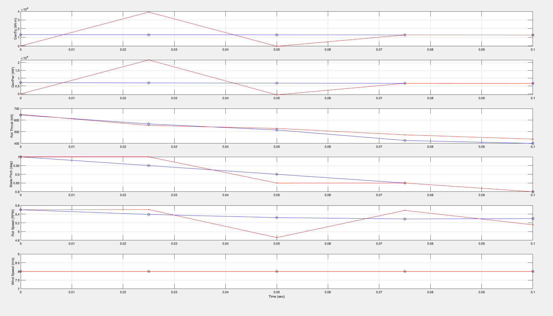
- Complete mismatch in Generator Torque i.e. between Generator Torque as input to the simulink model and the output from simulink model
- Complete mismatch in Generator Power
- Initial mismatch in Blade Pitch Angle i.e. between Blade Pitch Angle as input to the simulink model and the output from simulink model


Kindly guide me on this.
Thanks
Regards,
Muhammad Sharjil
Dear @Muhammad.Sharjil,
If I understand correctly, you are taking the generator torque, generator power, and blade-pitch angles from one simulation with PCMode = VSContrl = 5 and inputting them to the OpenFAST S-Function of a separate simulation in Simulink with PCMode = VSContrl = 4. And while the blade-pitch angles generally look OK, the generator torque and power are off.
I’m not sure why the latter is so far off. Have you confirmed that the inputs are correct?
The extrapolation of the inputs to the OpenFAST S-Function in Simulink could be related to the small mismatch at the beginning of the simulation, as discussed in the following forum topic: S-Function input output signal mismatch.
Best regards,
Hi @Jason.Jonkman
I have checked into inputs and found some anomalies. I adjusted the inputs and able to get improved results.
However, some initial mismatch in blade pitch angle, generator torque is observed.
The RPM and thrust are having differences
I want to have a comment on the results as if they are fine?
Thanks
Dear @Muhammad.Sharjil,
I’m glad that you are now getting improved results. The small differences over the first few time steps appear to be related to the extrapolation of the inputs to the OpenFAST S-Function from Simulink. Further along in the simulation, other small differences are leading to small differences in rotor speed (and thus likely azimuth angle, not shown), but overall, the comparison is quite decent I would say.
Best regards,
1 Like
Hi @Jason.Jonkman
I am using the AeroDyn_Driver for ad_BAR_CombinedCases in r-test.
I want to generate Cp, Ct and Cq curves against TSR and Blade Pitch Angle.
I have certain queries regarding the results.
Why is there a pattern in Cp and why it is not a fixed line?
What value to use for Cp for generating the Cp curve against TSR and Blade Pitch?
Same is the query for TSR and Power.
The images of file settings I have used are in the images.
Thanks
Dear @Muhammad.Sharjil,
From your AeroDyn input files, it looks like you have a few settings that will result in periodicity, including shear, shaft tilt, surge oscillation, and tower potential flow. For computing equivalent “steady state” values, I would suggest taking average values over a full revolution of the rotor.
Best regards,
Hi @Jason.Jonkman
Thanks for the response.
I this time used
WakeMod = 1 (instead of 2)
TwrPotent = 0 (instead of 1)
This time, there is no oscillation in the response.
The steadystate value for Cp with the option TwrPotent = 0 is not the average or mean of the case with TwrPotent = 1.
Can you comment on which value to used to buildup a Cp surface w.r.t TSR and Blade Pitch Angle.
I have another query, how can I average the periodicity in Cp curve with azimuth to get a mean value.
Thanks