Dear Jonson
Please tell me the corresponding of the outputs “q_DrTr” and “QD_DrTr” (FAST 7) to FAST V8
Sincerely yours
Dear Jonson
Please tell me the corresponding of the outputs “q_DrTr” and “QD_DrTr” (FAST 7) to FAST V8
Sincerely yours
Dear @Ali.Elyaakoubi,
These outputs parameters are named the same between FAST v7 and FAST v8. In FAST v8, these output parameters are available through the ElastoDyn module.
Best regards,
Thank you so much Mr Jason
Please, what means and what is the corresponding of these outputs in FAST 8/
QD_B1F1, QD_B2F1, QD_B3F1, Q_B1F1, Q_B2F1, Q_B3F1 and QD_GeAz
Sincerely
Dear @Ali.Elyaakoubi,
Here are brief descriptions:
Q_B#F1 for # = 1,2,3 - displacement of the 1st blade flapwise bending mode degree of freedom for blade #QD_B#F1 for # = 1,2,3 - first time-derivative (velocity) of the 1st blade flapwise bending mode degree of freedom or blade #QD_GeAz - first time-derivative (rotational speed) of the generator-azimuth degree of freedom; note that the generator azimuth state is expressed on the low-speed shaft side of the shaft rather than on the high-speed shaft side of the gearbox.Much more information is provided in the ElastDyn Theory Manual: 4.2.7. ElastoDyn Users Guide and Theory Manual — OpenFAST v3.5.2 documentation.
Best regards,
Thank you so much Mr @Jason.Jonkman
Please what is the difference of ‘QD_GeAz’ to ‘RotSpeed’ and ‘GenSpeed’
Sincerely yours
Dear @Ali.Elyaakoubi,
Essentially, GenSpeed is expressed on the high-speed shaft side of the gearbox, so, GenSpeed = QD_GeAz*GBRatio plus the conversion from rad/s (internal units used by QD_GeAz) to rpm (external units used by GenSpeed) that includes a multiplication by 30/pi rpm/(rad/s).
RotSpeed is expressed on the low-speed shaft side of the gearbox, but additionally includes the rotation rate of the drivetrain torsional flexibility (if enabled), i.e., RotSpeed = QD_GeAz + QD_DrTr (plus the conversion from rad/s to rpm).
Best regards,
Dear @ Jason.Jonkman,
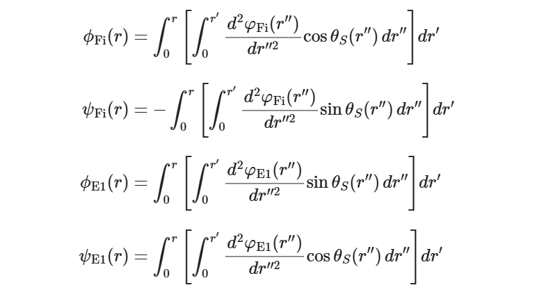
Based on my understanding, the relationship between blade out-of-plane deflection, blade in-plane deflection, the 1st and 2nd flapwise bending-mode DOF displacements, and the 1st edgewise bending-mode DOF displacement is given by the following expression
Using the parameters provided in BLADE MODE SHAPES, I calculated the following values at the 61.5-meter position:
phif1(61.5) = 0.9731,
phif2(61.5) = 0.9783,
psif1(61.5) = -0.2302,
psif2(61.5) = -0.2314,
phie(61.5) = 0.2299,
psie(61.5) = 0.9720.
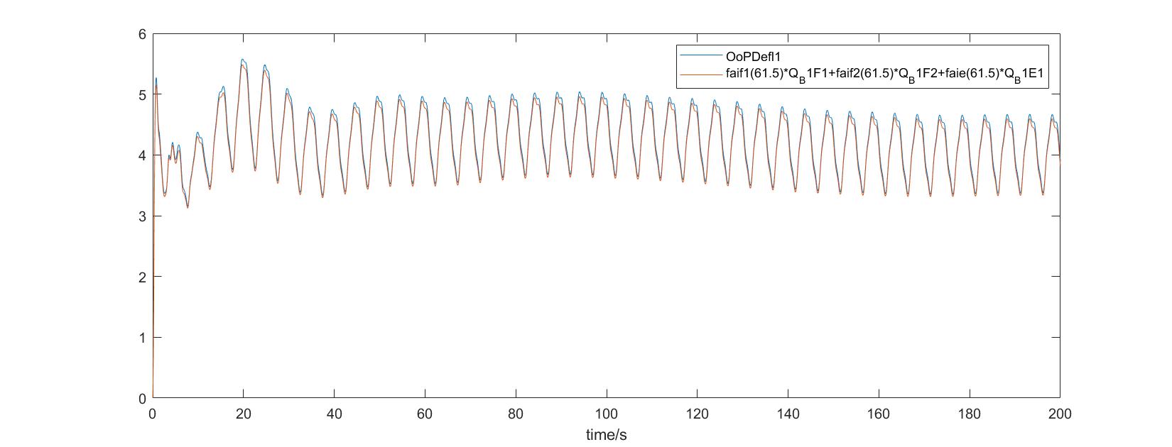
While the OpenFAST results for OoPDefl1 show good agreement with the values derived from Q_B1F1, Q_B1F2, and Q_B1E1 based on the above relationships, I observed a noticeable discrepancy for IPDefl1 under the same approach.
I was wondering if you could kindly help identify any potential mistakes in my understanding or calculations. I would greatly appreciate your guidance.
Thank you again for your reply and help.
Best regards,
Dear @Yingxin.Lv,
I agree with your equations except that the displacements u_out and u_in only refer to out-of-plane and in-plane when the blade pitch angle is zero. Is the blade pitch angle zero for your case for all time? If the blade-pitch is not zero, your calculations are valid in the blade coordinate that pitches with the root of the blade, which is not the same as out-of-plane and in-plane.
I haven’t checked your numerical values of phifi, psifi, phie and psie (which I presume are for the NREL 5-MW baseline wind turbine), but you should be able to confirm these numerical values based on their values calculated numerically within the OpenFAST source code (i.e., by compiling/running in debug mode are recompiling with these values printed out).
Best regards,