Dear All
Recently I have been trying to model a blade using BeamDyn. I have found that the stiffness matrix in “BeamDyn_Manual” has no coupling terms, while the stiffness matrix in “BeamDyn inputs from sectional beam properties” (Equation 17) has several coupling terms, e.g. K12, K16. I would like to know when we define BeamDyn’s input file, under what conditions do these coupling terms should be included? I have the same problem with the mass matrix, which seems more complicated in “BeamDyn inputs from sectional beam properties”. Are the angles θp, θs, and θi existing without deforming the blade, or are these angles generated after deformation?
Best Regards
Dear @Cao.Yuming,
The various coupling terms will be nonzero depending on the material properties of the cross section (especially whether the material is isotropic or anisotropic) and depending on what reference axis is used to define the cross sections (including the origin and orientation of the reference axes within the cross section). The angles θp, θs, and θi (principal axes of bending, principal axes of shear, and principal axes of inertia) are properties of the cross section, unrelated to blade deformation.
Best regards,
Dear @Cao.Yuming,
This document is likely the clearest description: https://openfast.readthedocs.io/en/main/_downloads/fd7a8bc10f2371a50828391f75170032/beamdyn_inputs_sectional_props.pdf, as well as the DYMORE manual it references. The angles refer to principal axes. If the angle is zero, this means that the principal axes are aligned with the reference axes and many of the coupling terms are zero (because SIN(0) = 0).
Best regards,
Dear @Jason.Jonkman
After the discussion with you, I also went through the previous similar topics on the forum. Here are the conclusions I came up with.
- Principle axes of bending, principle axes of shear, and principle axes of inertia origin from Tension center, Shear center and Center of mass, respectively.
- The elastic principal axes in BModes seem to be the principal axes of shear you are talking about, since its origin is the shear center.
- These three angles (θp, θs, and θi) are the angles between the corresponding principle axes and the Reference axes (XR-YR).
Please point out if there are any mistakes.
But another problem emerged. The terms and their interpretation are so different in the manuals of different programs, these are confusing to me.
Among the principal axes that may be related to stiffness, Bladed has only one called Principal axex, FOCUS has called Principal axes (bending stiffness), Principal axes (geometry), and there are only Principal axes (elastic) in BModes. Thus, it seems that there is only one orientation of the principal axes about the stiffness that can be derived in programs, but we have two angles. Since I can only get the blade structure data from FOCUS at the moment, how do I assign values to θp and θs.
Best regards,
Dear @Cao.Yuming,
I agree with your points 1-3.
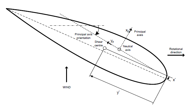
Some models have limitations and don’t support independent tension center, shear center, and mass center and/or independent principal axes of bending, shear, and inertia. BeamDyn supports the most general case with independence in all of these terms. BModes has limitations because transverse shear effects are ignored and isotropic material is assumed. I’m not familiar with the limitations of FOCUS, but I actually think the image from FOCUS makes more sense than the image from BModes, because the neutral axis and tension center typically refer to the same thing and because BModes does not consider transverse shear so locating “E” from the shear center does not make sense to me. It may be that the image from BModes is not shown properly.
Best regards,
Thank you, Jason. Since I have not worked on blade design, it is a bit difficult for me to find the available matching parameters. FOCUS outputs a variety of parameters, maybe I can find θp and θs from it.
Dear @Jason.Jonkman
After I read your answers under the previous question about BeamDyn, I got some new understanding. I sincerely hope you will point out any mistakes I may have made.
- In BeamDyn, the origin(key point) and the orientation of the axes of the local blade coordinate system can be set arbitrarily, even be outside the airfoil. It can also be defined in a known coordinate system such as principal axes of bending.
- Using principal axis of bending as the local blade coordinate system, (xc, yc) = (0, 0) and the structural twist angle is used as the “initial_twist” in BeamDyn. If the local coordinate system is not oriented with the local principle axes of bending, then “initial_twist” can not be represented by the structural twist angle.
- (kp_xr, kp_yr, kp_zr) represents the coordinates of the key point in the blade root coordinate system.
Best regards,
Dear @Cao.Yuming,
Yes, I agree with all of your points.
Best regards,
