Dear all,
I am performing a study on floating tidal turbine and I am hoping that fellow forum members could shed a light on how tower buoyancy is considered in OpenFAST.
I am referring to the MHK RM1 Reference Floater as a reference (GitHub) for a start. The following figure summarizes the output from the reference floater when analyzed as is (in still water condition), and it appears that buoyancy is well balanced by the platform weight & mooring tension as seen from the negligible platform heave displacement.
I updated the tower diameter to 3.50m as originally designed in “Methodology for Design and Economic Analysis of Marine Energy Conversion (MEC) Technologies” (Neary et al., 2014) while maintaining tower height of 15m. Recognizing that the increased submerged tower diameter will result in increased buoyancy, I increased the unit mass of the tower to balance the increased buoyancy force. A summary of relevant outputs are presented in figure below.
While the sum of vertical forces remain relatively small (≈ 3.7 kN), the platform seems to experience quite a significant heave, which suggests unbalanced upward forces. I wonder if I might have missed out some other source of buoyancy?
Hi Andhi,
Sorry for the confusion on the tower buoyancy.
The tower diameter that you mentioned in the 2014 paper is for the fixed bottom 2-rotor design, which uses a larger diameter cylindrical tower. The tower used on the floating platform has a faired shape, with more stiffness and less drag in the flow direction, and a smaller cross sectional area. The diameter selected for the AeroDyn tower input was intended to provide reasonable drag, based on the projected dimensions in the flow direction.
The tower and nacelle were included in the geometry for the platform potential flow body. This was done to get a more accurate frequency dependent added mass for these components. They are then also included in the potential flow body hydrostatic matrix, accounting for their buoyancy contributions in HydroDyn. It was a mistake to have buoyancy for the tower, nacelle, and hub also in AeroDyn, in the original input files on r-test. This has been corrected on the tight coupling development branch ( r-test/glue-codes/openfast/MHK_RM1_Floating/MHK_RM1_Floating_AeroDyn.dat at dev-tc · OpenFAST/r-test · GitHub ), but not yet for the main branch. Also note in the tight coupling branch that the added mass and pressure coefficients are also set to 0.0, since they are accounted for with the potential flow body.
It is up to the user to decide whether to include these loads in HydroDyn or AeroDyn, potentially with different advantages depending on the design.
Thanks,
Will
1 Like
Hi Will,
Thank you for your insightful reply! I understand now that the faired tower and nacelle is already included in the potential flow body. I’m still curious though as to why the platform appear to have unbalanced upward vertical force even though the resized tower is neutrally buoyant. I’m working on OpenFAST v4.0.4.
As it is rather difficult to work backwards from the ElastoDyn_Tower input, I wonder if there is a document that I could refer to obtain the faired tower dimensions?
Also, would you also be so kind as to share the WAMIT inputs that were used to derive the potential flow body?
Thanks & regards,
Andhi
Hi Andhi,
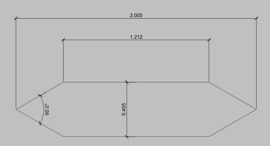
I don’t think there is any way to attach files in the forum here, but the image below shows the dimensions of the tower cross section used, with an area of 0.730 m^2. This is a rough idea of a faired tower for a tidal deployment, but has not been designed thoroughly.
If you look in the *.hst file, the value for 3,3 is 208.32 m^2. This multiplied by a density of 1025 kg/m^3 gives a heave hydrostatic stiffness of 213,526 N/m. The mooring system will also have some additional contribution to the total heave stiffness. I would expect for this platform as you change the submerged volumes and system masses, the equilibrium heave (looks like about ~0.3 m in your plot) would change roughly with that hydrostatic stiffness.
Thanks,
Will