Hi @Jason.Jonkman I believe I have managed to figure this out. I changed the GridWidth in TurbSim while still altering the structural damping. I will test some more cases and see.
Regards,
AOAW
Hi @Jason.Jonkman I believe I have managed to figure this out. I changed the GridWidth in TurbSim while still altering the structural damping. I will test some more cases and see.
Regards,
AOAW
Hi Jason:
I am still working on modelling the turbine for parked/idle condition.
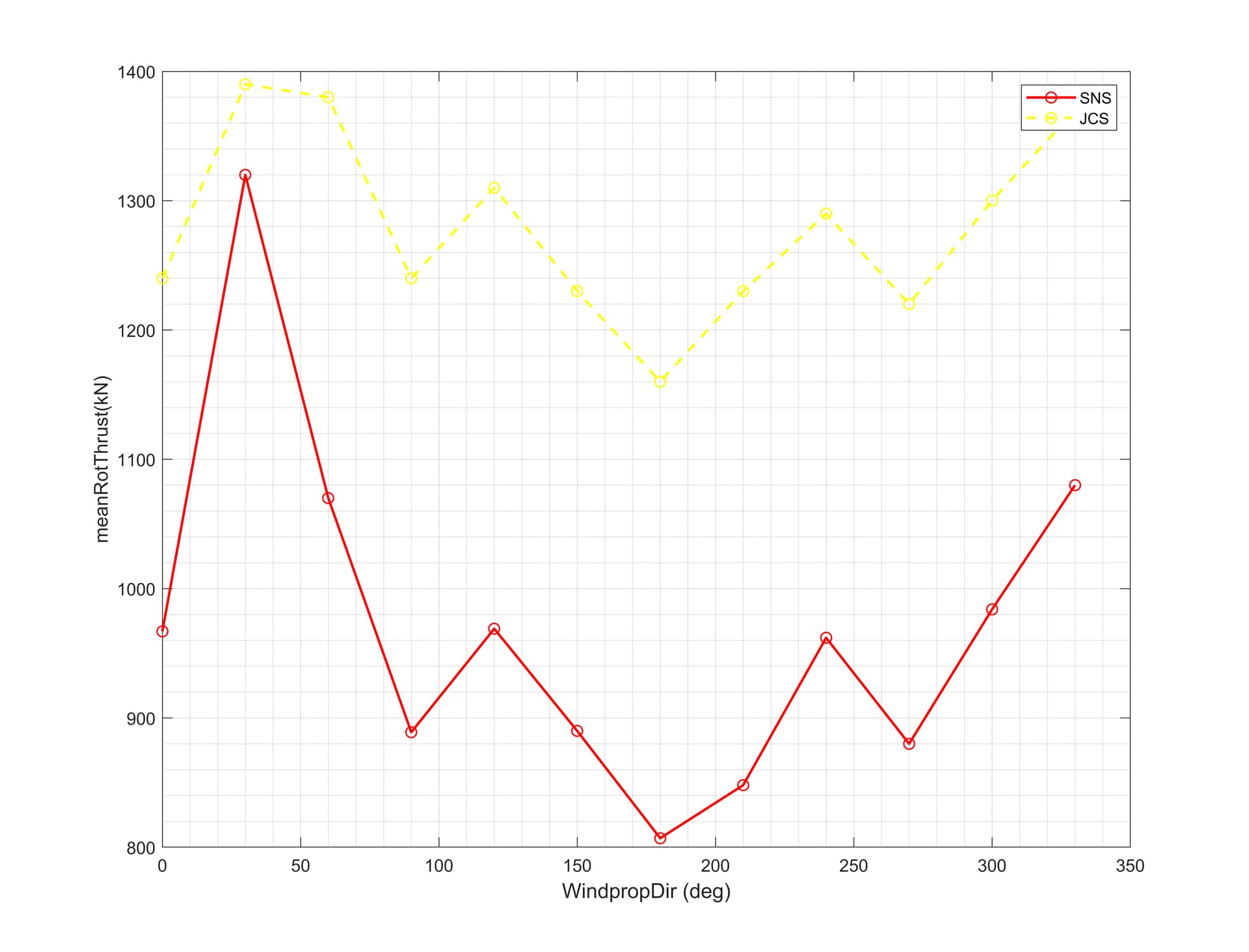
The only condition that I am changing for both cases is the wind direction. I have increased the wind speed from 0 to 330 (30 deg. increments) and taken the max values of a variable( from 6-random seeds) for each wind direction considered. One of the variables I am looking on is the thrust force on the rotor. I was expecting that the forces would give a constant plot so for example the force at 30 degree would be equal to the force at 330 degree (since their cosines, for example, are the same). However, the plot which I have attached show that the max value of the rotor thrust for wind direction of 30 degree is greater than the value at 330 degrees. In fact, it is the greatest of all the angles and the overall plot is not constant for the change in angles.
I would like to know if you have any idea why this could be so? I do not think it is due to the sea state or the small difference in TI, 9.7% and 10.6% respectively. Otherwise, I will set both the same for both locations, so that the only difference between the models is the angle.
See plot showing the maxRotThrust at both locations attached. The same thing also happens for rotor speed, so I have attached that plot as well.
Thank you.
Regards,
AOAW
Dear @Andre.White,
Can you clarify what you are plotting? What are SNS and JCS?
Maximum values are not always intuitive, but can sometimes be understood by the mean and standard deviations of the signal. So, I’m also curious what the mean and standard deviation values of rotor thrust and speed are for these wind directions. Can you share those figures as well?
Best regards,
Hi @Jason.Jonkman SNS is Scottish North Sea and JCS is Jamaica Caribbean Sea.
I have not done the plots for the mean and standard deviations. I will have to do them and get back to you.
Could you please elaborate on how the max values can be understood by mean and standard deviation?
Thank you.
Regards,
AOAW
Hi @Andre.White,
I just mean statistically, the maximum value is often approximated as the mean value plus some number of standard deviations above the mean value. And often the mean and standard deviation values are more intuitive to interpret directly.
Best regards,
Hi @Jason.Jonkman:
These are the mean and standard deviation plots for rotor thrust and rotor speed. It essentially shows same trend with max values at a wind direction of 30 deg. and the values are not constant for wind directions that are the same. Please let me know if you have any ideas why this is not the case.
Regards,
AOAW
Dear @Andre.White,
I’m a bit surprised that the mean rotor speed is nonzero for any of the wind directions, considering that the blades are feathered to 90 degrees, implying what I would expect to be zero mean torque. Have you disabled the generator torque and ensured that the blade pitch is in fact 90deg for all cases?
Best regards,
Hi @Jason.Jonkman. I believe I disabled he generator by setting VSContrl to 0. See generator settings that I used below:
The blade is feathered to 90 degrees for all blades.
Regards,
AOAW
Hi @Jason.Jonkman should I also turn off the generator DOF in ElastoDyn?
Regards,
AOAW
Dear @Andre.White,
Assuming that your simulation is not more than 4000 s long, your simulation set up should results in no generator torque. Disabling the generator DOF would result in the rotor parked in position, regardless of the loads applied.
If feathering the blades to 90 degrees results in a net rotor speed, perhaps the pitch needs to be feathered to a bit different pitch angle to better idle the rotor?
Best regards,
Hi @Jason.Jonkman thank you. Yes my simulation time is less than 4000 s long. I will play with the blade pitch angle and see if that gives mean rotor speed of zero.
Thank you.
Regards,
AOAW
Hi @Jason.Jonkman I changed the blade pitch angle to 92.5 deg. and ran a few cases. For one of the cases, wind direction at 300 deg. a mean rotor speed of zero was recorded but other wind directions showed that the mean rotor speed was above/below zero. I think changing pitch angle for every change in wind direction would be too cumbersome.
Any further thoughts? I was trying to find a paper on how wind direction change affects turbine behaviour and only found one.
I have two other queries, which I will send separately shortly.
Thank you.
Regards,
AOAW
Dear @Andre.White,
Is there a pitch angle that provides close to zero mean rotor speed for all wind directions? If so, I’d suggest using that.
Best regards,
Hi @Jason.Jonkman I am not sure. Investigating now. So let me ask one more question:
Is it that when the turbine is idle the mean torque should be zero and hence the mean rotor speed should also be zero?
Regards,
AOAW
Yes, that is correct.
Hi @Jason.Jonkman about the pitch angle that gives mean rotor speed close to zero for all wind directions, this was the outcome.
For all wind directions but zero degrees I obtained mean rotor speed of zero with a pitch angle of 91.5 degrees. However, for zero degree wind direction, a pitch angle of 80.5 degrees gave mean rotor speed of zero.
I think I will run the simulations with these two angles. Please let me know what you think?
Thank you.
Regards,
AOAW
Dear @Andre.White,
I would guess it would be pretty rare for the pitch angle during parked/idling conditions to depend on the wind direction. So, I would choose the pitch angle that works best (resulting in zero mean rotor speed) for the majority of wind directions, which it sounds like is 91.5deg in your case.
Best regards,
Thanks @Jason.Jonkman .
Regards,
AOAW
Hi @Jason.Jonkman if I would like to simulate a parked/fixed (not idling but rotor) would I do that by activating the high speed brake and if so are these the settings to use:
---------------------- HIGH-SPEED SHAFT BRAKE ----------------------------------
1 HSSBrMode - HSS brake model {0: none, 1: simple, 3: user-defined from routine UserHSSBr, 4: user-defined from Simulink/Labview, 5: user-defined from Bladed-style DLL} (switch)
10 THSSBrDp - Time to initiate deployment of the HSS brake (s)
9999.9 HSSBrDT - Time for HSS-brake to reach full deployment once initiated (sec) [used only when HSSBrMode=1]
9999.9 HSSBrTqF - Fully deployed HSS-brake torque (N-m)
---------------------- NACELLE-YAW CONTROL -------------------------------------
--------------------- GENERATOR AND TORQUE CONTROL ----------------------------
5 VSContrl - Variable-speed control mode {0: none, 1: simple VS, 3: user-defined from routine UserVSCont, 4: user-defined from Simulink/Labview, 5: user-defined from Bladed-style DLL} (switch)
1 GenModel - Generator model {1: simple, 2: Thevenin, 3: user-defined from routine UserGen} (switch) [used only when VSContrl=0]
95.756 GenEff - Generator efficiency [ignored by the Thevenin and user-defined generator models] (%)
True GenTiStr - Method to start the generator {T: timed using TimGenOn, F: generator speed using SpdGenOn} (flag)
True GenTiStp - Method to stop the generator {T: timed using TimGenOf, F: when generator power = 0} (flag)
9999.9 SpdGenOn - Generator speed to turn on the generator for a startup (HSS speed) (rpm) [used only when GenTiStr=False]
4000 TimGenOn - Time to turn on the generator for a startup (s) [used only when GenTiStr=True]
9999.9 TimGenOf - Time to turn off the generator (s) [used only when GenTiStp=True]
Thank you.
Regards,
AOAW
Dear @Andre.White,
To simulated a parked rotor, the simplest approach is to disable the generator degree of freedom in ElastoDyn (GenDOF = False) and set the initial rotor speed to zero (RotSpeed = 0). This will ensure that the generator never spins regardless of any torque applied to the shaft.
If you keep GenDOF = True, then applying the high-speed shaft brake can be used to model the parked rotor, with possible slippage if a torque gets to high and overcomes the brake torque. But normally the high-speed shaft brake model is used to simulate a shutdown scenario with a mechanical brake. Regardless, to model a parked rotor with the high-speed shaft brake, I would think you’d want turn on the brake at the start of the simulation (THSSBrDp = 0 s) and ensure that it is already fully deployed (THSSBrDT = 0 s). You must also set a realistic value for the full deployed brake torque (HSSBrTqF), above which slippage would occur.
Best regards,