Hi Everybody,
I hope somebody might have an answer to this problem I am facing. I have simulation results of a wind-turbine with a constant wind-field.
At first I turned off the edgewise DOF for the blades, the flapwise DOFs are turned on. Therefore I get a Tip-Acceleration in local z-Direction that is similar to my calculations of centripetal acceleration. That is alright.
No the problem: I turned on the edgewise DOF and ran the Simulation again. In my Tip-AL I can the turning frequency of the Rotor with an high amplitude
(Tip to Tip: about 3.8 m/s^2).
My conclusion is, that there must be a relation of TipAl in z-direction and my turning frequency of the rotor. As gravitational influence is not possible, I am wondering what it might be. In Addition the amplitude of TipAl in y-direction is comparably small.
Thanks for your help in advance.
Bye,
Kai
Dear Kai,
I’m sorry, but I’m not sure what you mean when you say, “in my Tip-AL I can the turning frequency of the Rotor with an high amplitude.”
The blade-tip acceleration outputs from FAST will include contributions from rotor rotation, blade deflection, and motion from other turbine DOFs (e.g, tower deflection, yaw motion, etc.).
Best regards,
Dear Jason,
thanks for your reply.
That is exactly what I thought. So when the blade deflects in flapwise and edgewise direction there will be influence of all directions in the local Z-tip acceleration. My simulation results look like this:

The Peaks occur in the same frequency as my rotational frequency of the rotor. The Blade deflects with the same frequency but unfortunately I have no explanation for the high amplitude of this signal, because the amplitudes of the other acceleration signals are rather small and the deflections are small as well.
This only occurs when I turn on the edgewise deflection DOF…
Maybe is there any formula for the relation between deflection and the local Z-acceleration?
Thanks a lot for any help…
Kai
Dear Kai,
The geometric nonlinearities in the FAST blade model determine a relationship between flapwise and edgewise deflections and the axial deflection. Can you plot the flapwise, edgewise, and axial blade-tip deflection as well (TipDxb1, TipDyb1, and TipDzb1)?
Best regards,
Dear Jason,
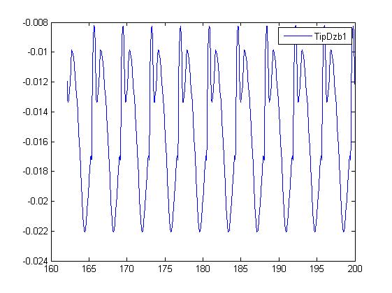
of course I can plot these values: I can’t identify anything strange in these plots.


TipDz.jpg
For further information:
TipRad = 45.184m; HubRad = 2.26m
The deflection angle about the y-axis is between 1.8 and 2.8 deg
The deflection angle about the x-Axis varies between -0.7 and 0.7 deg
I was assuming that there is a relation, so that with the small angles I could use standard rotation matrices for coordinate transformation.
For the desired acceleration in z-direction I got this relation:
TipAlzb1 = -sin(TipRD-y)* Accel-x + cos(TipRD-y)*sin(TipRD-x)*Accel-y + cos(TipRD-y)*cos(TipRD-x)TipRadomega^2
, where Accel-“i” is the acceleration in undeflected coordinates in direction of “i”.
The would really like to understand this phenomenon.
Cheers,
Kai
Dear Kai,
While your equation may not be exactly correct, I think your on the right track. The flapwise, edgewise, and axial deflections in the undeflected frame are all contributing to the acceleration in the axial direction of the deflected blade. You can probably estimate the accelerations in the undeflected frame as Acceleration = (Displacement Amplitude)omega^2, where omega is the dominate frequency, which looks to be about omega = 2pi/(4 s) = 1.57 rad/s. How do the displacement amplitudes in the flapwise, edgewise, and axial directions change when you disable the edgewise DOF?
Best regards,
Dear Jason,
thanks for your hint. I calculated the accelerations in the undeflected frame as the second derivative of the displacements in the undeflected frame.
I turned off the Edge-DOF and saw made two interesting observations.
1st) The TipAl in y-Direction still has a countable size (about 0.7 m/s^2) , although deflection in this direction is zero.
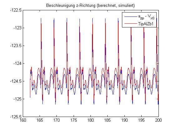
2nd) I made some arbitrary calculations ans I found the relation [Centripetal - *V_x0 ] to be well aligned with the TipAl - Z - B1. (Please see Plot) where V_x0 is the first derivative of the displacements in x-direction in the undeflected frame. Now that’s kinda strange.
In my former idea I forgot, that the coordinate systems are rotating and are not constant. I guess I should regard that fact.
Anyways - I wish all of you a pleasant weekend.
Kai
Dear Kai,
Regarding point 1, the tip acceleration in the y-direction is likely the result of tangential acceleration due to variable rotor speed.
I’m not sure what you are saying in point 2.
Best regards,
Dear Jason,
in point 2 I took my calculated centripetal acceleration (omega^2*R) and subtracted the velocity of the Tip in x-direction. I found that by an mistake I did in my file. But I really wonder why both values are well aligned.
Best regards,
Kai