We are coupling our inhouse structural solver with Aerodyn.
We want to include the moment due to the offset between FE nodes and AC.
After going thorough several discussions in this forum and the documentation, I have understood that - BlCrvAC and BlSwpAC are the offsets from pitch axis. I want to obtain these coordinates and their motions in terms of global reference frame. Because we already have our FE node coordinates and motions in terms of global reference frame.
As I understand it involves several successive transformations.
Pitched position to Blade local - rotation using pitch angle
Blade local to pitch axis - rotation using BlCrvAng
Pitch axis to Rotor plane - rotation using Precone
Rotor plane to hub axis - rotation using Azimuth and translation using BldSpan and
Hub to Nacelle - rotation using shftTilt and translation using OverHang and Twr2Shft
Nacelle to Global - translation using tower height
Please confirm if these transformation are correct provided my understanding is valid.
I referred to this document
I generally agree with what you are saying; just a few comments:
I would say that your transformations are backwards and that the successive transformations are from the ground (global) to the blade, not the other way around. In terms of rotations, these are just transposes of each other. But the equations you copied from the ElastoDyn Theory Manual are backwards from what you describe.
From the hub to the blade node, the sequence should be pitch angle, followed by BlCrvAng, not the other way around.
Your transformations miss the BlCrvAC and BlSwpAC offsets in step 1, as well as the HubRad in step 4.
Your transformations miss any effect of structural deflection from elasticity.
Regarding the symbols in the ElastoDyn theory manual, q_R, q_P, and q_Y are the roll, pitch, and yaw displacements (rigid-body rotations) of the platform. These and other ElastoDyn structural DOFs are documented in FASTDOFs.xls.
Regardless, I would think your structural FE solver would compute all of these transformations internally, and so, you shouldn’t need to know what ElastoDyn is doing exactly anyway if you goal is to replace ElastoDyn with your own FE solver.
What is the datastructure that contains the deflection of AC in blade coordinates ? Does AeroDyn track it ?
Once this deflection is known - for every time step I can add that to my AC coordinates and then carry on the transformation.
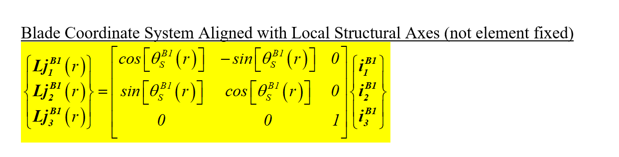
Yes as I understand, I don’t need TransMat. For all the above rotation transformations - Direction cosine matrix (DCM) would be required for each successive ones (of course in the backward order).
For example - for a rotation about a common z axis, the DCM would look like
Structural deflections of the blade in OpenFAST are tracked by the structural solver (ElastoDyn, BeamDyn). The motions (positions/orientations, velocities) are passed to the aerodynamic solver (AeroDyn). AeroDyn expects the motions to be received at the aerodynamic analysis nodes, which on the blade are at the aerodynamic centers. Within OpenFAST, spatial mesh-ot-mesh mapping is used to transfer the data from the structural nodes to the aerodynamic nodes.
I agree that that you can track your own DCMs from your own structural solver and pass the successive DCM to AeroDyn.
Dear @Jason.Jonkman, thank you for your replies to date.
Above you state that: “Structural deflections of the blade in OpenFAST are tracked by the structural solver (ElastoDyn, BeamDyn). The motions (positions/orientations, velocities) are passed to the aerodynamic solver (AeroDyn). AeroDyn expects the motions to be received at the aerodynamic analysis nodes, which on the blade are at the aerodynamic centers”. This seems very clear to me.
In another thread (https://forums.nrel.gov/t/how-to-import-hub-motions-to-aerodyn/1350/2) you have documented the variables which an external structural solver should pass to AeroDyn. However, this message does not seem to mention positions (i.e. points in 3D space). It mentions displacements (i.e. changes in position) and orientations, and velocities, but it does not explicitly mention position.
By way of background, I am currently updating our structural solver to supply AeroDyn with the aerodynamic node positions, rather than the structural node positions.
Q2: Do you think that there is likely to be any significant difference between the displacements of the structural nodes (which I am currently passing) and the displacements of the aerodynamic nodes (which I intend to pass), assuming that there is a physical separation between the shear and aerodynamic centrs on the blade profile. For example, I think that any blade twist occurring about the pitch could lead to small differences between the translational displacements of the structural nodes and aerodynamic nodes.
Regarding (1), the displacements fields passed as inputs or outputs of mesh data structures within OpenFAST are expressed in global coordinates and are relative to the reference positions of the mesh nodes. So, the global position is simply the sum of the displacements and the reference positions.
Regarding (2), OpenFAST uses its spatial mesh-to-mesh mapping utility to transfer data from the source mesh (input or output of a module) to the destination mesh (output or input of a module). When transferring displacements, if the reference positions of each mesh are not aligned (e.g., due to offsets between the aerodynamic center and elastic center as in your example), rotational motions will influence the translational displacements, assuming rigid-body kinematics. Likewise, forces will contribute to moments because of the offsets, which act like moment arms. For more information on the spatial mesh-to-mesh mapping utility of OpenFAST, see the following paper: https://www.nrel.gov/docs/fy14osti/60742.pdf, with a couple updates in: https://dx.doi.org/10.2514/6.2015-1461. If you are coupling your own structural solver to AeroDyn, rather than figuring out how to implement all of these spatial mesh-to-mesh mapping relationships yourself, I would instead define a mesh in your structural solver and call OpenFAST’s mesh-mapping utilities directly to transfer the source/destination data between meshes.
So mapping our structural data to FED data structure and utilizing the AeroDyn_Driver_Subs.f90 subroutines for mesh update (Dvr_TimeStep) is a good direction to go ahead ?
I have not an fully reviewed how the standalone AeroDyn driver sets up its mesh data structures through FED and calls AeroDyn. I think it would be better to review how ElastoDyn or BeamDyn set up their meshes and how the OpenFAST glue code calls the mesh-mapping routines to transfer ElastoDyn/BeamDyn outputs/inputs to AeroDyn inputs/outputs, given that is what you are trying to mimic.