Dear Community,
I modeled a multi-body floating wind turbine platform (Nbody=5) for the first time. I calculated the potential flow files (PotFile) using AQWA, setting the center of gravity (COG) of each body to Z=0 in AQWA. The center of buoyancy(COB) was automatically calculated by AQWA. To avoid double counting, I followed the suggestion in the following forum post and modified the platform center of gravity position: hydrodynamic model for semisubmersible FOWT - #7 by Jason.Jonkman
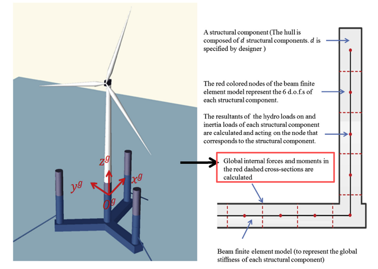
Below is a schematic diagram of the model and the calculation of AQWA. The blue cross marks indicate the center of buoyancy positions, and the black squares indicate the center of gravity positions:


I currently have the following questions for advice:
First, when I ran the simulation with the above settings, the platform experienced large pitch and roll displacements, as shown below, what could be causing these large displacements?
Second, for a multi-body model, does ElastoDyn also require separate center of gravity values for each floating body (as in HydroDyn), or is it sufficient to define only one overall platform center of gravity?

My relevant HydroDyn settings are as follows:
---------------------- FLOATING PLATFORM ---------------------------------------
1 PotMod - Potential-flow model
1 ExctnMod - Wave-excitation model
1 ExctnDisp - Method of computing Wave Excitation
10 ExctnCutOff - Cutoff frequency (Hz)
0 PtfmYMod - Model for large platform yaw offset
0 PtfmRefY - Platform reference yaw offset (deg)
10 PtfmYCutOff - Cutoff frequency (Hz)
36 NExctnHdg - Number of platform yaw angles
1 RdtnMod - Radiation memory-effect model
80 RdtnTMax - Analysis time for radiation kernels (sec)
“DEFAULT” RdtnDT - Time step for radiation kernels (sec)
5 NBody - Number of WAMIT bodies
1 NBodyMod - Body coupling model
“../../HydroData/study” PotFile - Root name of potential-flow data
1 WAMITULEN - Characteristic body length scale (m)
-23.75 -23.75 0 47.54 0 PtfmRefxt - xt offset of body reference points (m)
-41.14 41.14 0 0 0 PtfmRefyt - yt offset of body reference points (m)
-14 -14 -20 -14 -10 PtfmRefzt - zt offset of body reference points (m)
0 0 -15 0 0 PtfmRefztRot - Rotation about zt (deg)
4277 4277 13975 4277 839 PtfmVol0 - Displaced volume (m^3)
0 0 0 0 0 PtfmCOBxt - xt offset of COB (m)
0 0 0 0 0 PtfmCOByt - yt offset of COB (m)
My relevant Elastodyn settings are as follows:
---------------------- TURBINE CONFIGURATION -----------------------------------
3 NumBl - Number of blades
149.693 TipRad - Blade tip radius (m)
2.443 HubRad - Blade root radius (m)
-3 PreCone(1) - Blade 1 cone angle (deg)
-3 PreCone(2) - Blade 2 cone angle (deg)
-3 PreCone(3) - Blade 3 cone angle (deg)
0 HubCM - Hub mass offset (m)
0 UndSling - Undersling length (m)
0 Delta3 - Delta-3 angle (deg)
0 AzimB1Up - Azimuth for blade 1 up (deg)
-8.08262 OverHang - Overhang length (m)
0.0 ShftGagL - Shaft strain gage location (m)
-8 ShftTilt - Rotor shaft tilt (deg)
2.361 NacCMxn - Nacelle CM x-offset (m)
0.014 NacCMyn - Nacelle CM y-offset (m)
2.113 NacCMzn - Nacelle CM z-offset (m)
2.361 NcIMUxn - Nacelle IMU x-offset (m)
0.014 NcIMUyn - Nacelle IMU y-offset (m)
2.113 NcIMUzn - Nacelle IMU z-offset (m)
2.675117 Twr2Shft - Tower-top to shaft vertical distance (m)
168.9 TowerHt - Tower height (m)
18.2 TowerBsHt - Tower base height (m)
0.0686 PtfmCMxt - Platform CM x-offset (m)
0 PtfmCMyt - Platform CM y-offset (m)
-11.774 PtfmCMzt - Platform CM z-offset (m)
0 PtfmRefzt - Platform reference point z-offset (m)
Best regards,