IEA 15 MW FOWT-Discrepancies in Tip-Speed Ratio and Blade Pitch Angle between Steady and Turbulent Wind Fields

Dear all,

I am simulating the IEA 15 MW RWT FOWT on the UMaine floater and my goal is to compare it with the Bottom-Fixed counterpart (BF) so as to identify the reasons behind the changes in its power production characteristics. The simulations are done using steady and turbulent wind field, with a turbulence intensity of 10% for all wind speeds between 4 and 24 m/s. In the case of the FOWT, the nacelle fore-aft velocity feedback is on, while the torque controller emoloys the TSR tracking PI control logic.

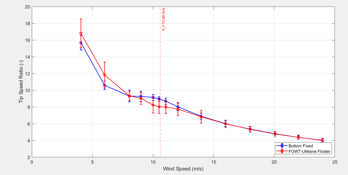
When simulating steady wind conditions, the TSR variation of both configurations is the same up to the peak shaver wind speeds (~9.5 m/s), while the blade pitch angle of the FOWT is lower up to 6 m/s, due to the parallel compensation control term. Up to the peak shaver region, the two configurations have the same blade pitch. As far as the rotational speed is concerned, both WTs have the same variations up to the peak shaver, while between 4 and 6 m/s, the rotor speed is constrained to the minimum rotational speed. The results can be represented in the following three figures.

image

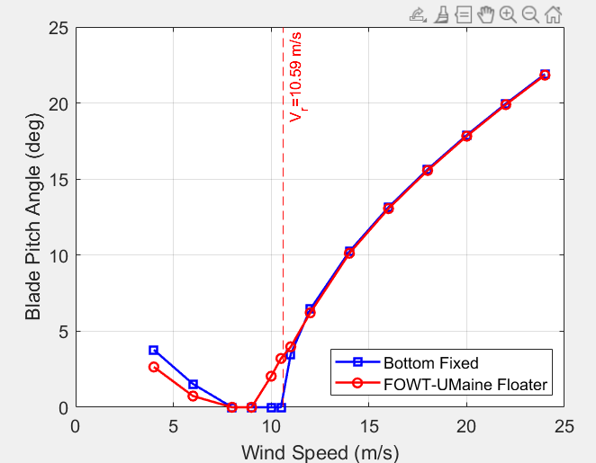
However, I have issues in identifying the motive forces for the turbulent wind results. Firstly, the TSR of the FOWT higher than the BF for the whole 1.5 region (i.e. up to 8 m/s), while nearly equal between 8 and 9 m/s before the peak shaver is enabled, a fact which can be explained by the wind speed variations due to turbulence. For the case of the blade pitch, nearly the same results are obtained with the case of steady wind, with the exception of earlier blade pitching due to the nacelle fore aft velocity which needs to be countered. However, I cannot explain the difference in the rotational speed, which is not equal to the minimum rotational speed of the turbine for wind speeds between 4 and 6 m/s.
Apparently, the tracked TSR changed and, combined with the wind speed variations, the rotational speed has to increase from the rotor rotational speed constraint.


Therefore, my questions are:
1.) How is the generator torque controller TSR reference, determined and why it has changed due to the wind field type change? Since the turbulent wind fields are the same for the two turbines, the TSR reference seems logic to be the same for the FOWT and the BF as in the steady wind case.
2.) It seems rather unusual for the rotational speed to increace in reference to the minimum rotational speed constraint. Is it logical to happen?
3.) Overall, are my results reasonable?

Best regards,
Ioannis Voultsos.

Hi Ioannis,

  1. The generator torque control TSR reference is determined using the wind speed estimate and the control parameter VS_TSRopt (ROSCO/ControllerBlocks.f90 at 5d201855f57d0773ad8304349257db19c6db6af2 · NREL/ROSCO · GitHub). Comparing the wind speed estimate signal (WE_Vw in the .dbg file) at low wind speeds would be a good idea to hone in on the differences.

  2. The minimum rotor speed is enforced by changing the reference generator speed (one line below the link above). Since we can’t track that reference perfectly, differences around that reference are expected. We typically use a pretty slow torque controller so the power variations are not too much.

  3. Your results are clear and seem reasonable to me. The only curious part is the low wind speed regions, which you seem to be investigating.

Please feel free to follow up with any additional findings/questions for us and others on the forum.

Best, Dan

1 Like

Dear Daniel,

Thank you for your response.

Is there a script on Github or elsewhere for opening .dbg files, as like .outb files? Importing them on e.g. MATLAB is a pretty much complicated task.

Best regards,
Ioannis.

EDIT: I used the ROSCOout2Matlab function and works ok.

Dear Daniel,

This is the comparison of the average values of the wind speeds estimated by the wind speed estimator (WSE) block for the Bottom Fixed (BF) and the FOWT for the wind speeds examined:

It should be noted that the standard deviation of the FOWT estimated wind speed is higher for wind speeds below 14 m/s, where the BF and the FOWT pitch controllers operate with the same logic. For the sake of completeness, I also attach the Cp comparison between the BF and the FOWT turbines.

At low wind speeds (i.e. between 4 and 6 m/s), it can be seen that the estimated wind speed is higher than its actual value, which results in increasing the rotational speed setpoint of the generator torque control, thereby explaining the observations in the rotatioanl speed variation. The results suggest that, due to the reduction of the blade pitch angle, so as to keep the floater pitch at a near zero value, has an impact on the estimated wind speed by the controller, which makes sense to increase. The increase of the rotational speed setpoint also explains the increase of the TSR in this wind speed range.

However, things are a bit more complicated between 7 and 9 m/s (Region 2 before the peak shaver). The estimated wind speed for the FOWT is closer to that of the BF, albeit a bit higher. At 8 m/s, the discrepancies between the two configurations in terms of rotational speed, wind speed estimate, blade pitch and Cp are comparatively small. The FOWT power loss can be attributed to small Cp variations and to the static floater pitch angle which around 2.2 deg.

My issue is the windspeed of 9 m/s. As it seems, the WSE FOWT wind speed is somewhat larger than the one of the BF, therefore resulting in an increase in the rotational speed setpoint as per line 56 of the ROSCO controller algorithm. On the same time, the parallel floating feedback term increases the blade pitch angle so as to limit the floater pitch angle (average value=2.8 deg at 9 m/s). Then, the provisional TSR, which is used on the Cp calculation via the Cp surface, tends to increase due to the increase in rotational speed and the decrease of the inflow wind speed due to the floater pitch angle.

Thus, the Δωg error obtained by the plant controller block causes a reduction in the generator rotational speed and consequently in the rotor rotational speed. In additional loops, the rotational speed is further reduced, obtaining a reduced value for the FOWT in comparison to the BF. Finally, due to the reduced Cp and the reduced rotational speed, the FOWT power output is reduced.

To conclude:
1.) As it seems, the motive force for the wind speed estimator block is the blade pitch angle set by the pitch saturation routine and the parallel compensation term. When the blade pitch angle reduces towards 0 deg, the wind speed increases, while the opposite happens when the blade pitch angle increases. Is my understanding correct or am I missing vital information about the controller operation?
2.) Am I missing something from the observation explanations for wind speeds 4-6 m/s and 7-9 m/s? Is my rationale correct, especially about the wind speed of 9 m/s?
3.) Is the controller tuning logic hindering the performance of the FOWT under low wind speeds (or negligible floater pitch angles) or is it indeed the influence of the blade pitch angle on the WSE block?

Best regards,
Ioannis Voultsos.

Hi Ioannis,

I typically use these scripts in a python environment: ROSCO/output_processing.py at main · NREL/ROSCO · GitHub

Best, Dan

1 Like

Hi Ioannis,

  1. Based on my understanding, where the turbine is currently on the Cp surface (blade pitch, TSR) largely determines the wind speed estimate. Larger pitch angles usually lead to larger wind speed estimates, but it’s more complicated (as you’ve seen) in this near-rated region.

  2. The floating feedback term shouldn’t have a mean pitch angle. If it does, then perhaps it should be fixed. I would guess the mean pitch angle is due to peak shaving. Even though it doesn’t start until 9.5 m/s, it will be active often in a turbulent simulation.

  3. I’m not sure what you mean by hindering performance, but we do know that the wind speed estimate is not always perfect at low wind speeds. It shouldn’t affect the torque control much because that set point is usually saturated at a lower limit. We have seen that there are better ways to compute the Cp surface and optimize the pitch angles at low wind speeds. (See section 5.3 here for more information about that: WES - A reference open-source controller for fixed and floating offshore wind turbines)

If you have suggestions for improvements, please feel free to start a discussion here, and we can dig into the code more.

Best, Dan

1 Like

Hi Ioannis,

I just wanted to chime in with a couple more thoughts here:

  1. In your figure comparing the average wind speeds, what is the black dashed line plotting? It is generally best to compare to the rotor averaged wind speed (RtVAvgxh), as this is indicative of what the WSE is tracking. A good sanity check might be to look at the time histories of the WSE and RtVAvgxh for the floating results at ~4m/s and confirm that they are consistent with the mismatch plotted above.

  2. As you are discovering, the near-rated operation is uniquely complicated. Between the nonlinear effects of added peak shaving, the complexity of the transition between the torque and pitch controllers, and the fact that the turbine dynamics are perhaps most hectic in this region, I would be very surprised if the FOWT and FB match up well. I think it is perhaps best to look at each turbine’s behavior individually to make sure you “agree” with what the controller is doing, and then consider whether any changes might be made such that the turbine’s final behavior matches more to your liking.

  3. To echo Dan, your results do seem clear and reasonable to me as well, and the low wind speed differences might deserve a slightly deeper look. There is certainly a lot of interplay between the controller and FOWT dynamics that can be hard to work through, but it seems to me that you have a good grasp on things.

Generally - thanks for your deep dive into the inner workings of ROSCO and how its performance compares across the FB and FOWT turbines – this sort of thing is very insightful, even to those of use who work with these models daily. We’re always welcome to hear suggestions and improvements!

Cheers,
Nikhar

1 Like

Dear Daniel and Nikhar,

Thank you for your responses. Your hints were valuable for my understanding. The black dashed curve is there for comparison reasons and shows the actual wind speed at the center of the Mann box (i.e. 4,6,8 m/s etc. ). It is a y=x line, which helps me understand what is the WSE deviation in comparison to the average wind speed at the Mann box center.

The comparison between the wind speed estimate and the RtVAvgxh values are shown in the charts below for turbulent wind according to Mann Turbulence method, TI=10 % and for wind speeds 4 and 8 m/s respectively.

(4 m/s, Seed 1209)

(4 m/s, Seed 600)

(8 m/s, Seed 1209)

(8 m/s, Seed 600)

As it seems, the WSE predicts higher wind speeds for the range of 4-6 m/s, while for 8 m/s, the WSE is correct for one of the presented seeds. Discrepancies can be attributed to the turbulence realisation, since for the third seed I used, the WSE and the RtVAvgxh were correleated. Nevertheless, the results generally show that after 8 m/s, the WSE is able to provide a good prediction of wind speeds.

My guessing is that the WSE deviation at low wind speeds caused by the WSE algorithm implementation. Is this indeed the case?

Best regards,
Ioannis Voultsos.

Hi Ioannis,

I think something might be wrong with your control library or inputs. Are you using the latest version of ROSCO?

This looks like a wind speed estimator issue we fixed a while back. It should look like this at 4 m/s:

image

Best, Dan

Dear Daniel,

Probably, I am using ROSCO v.2.4.1 because I downloaded the model files in early December 2021.

Just to make sure, in order to move to ROSCO v2.5.0, I should replace the existing DISCON-Monopile.IN, IEA15MW-Monopile.yaml, DISCON-UMaineSemi.IN and IEA15MW-UMaineSemi.yaml files with the ones from ROSCO v.2.5.0, without making a substitution of the DISCON.dll file that I have so far in my ServoData folders. Is that correct?

Best regards,
Ioannis Voultsos.

Hi Ioannis,

You have to replace the DLL along with all the input files for the newest version. I would be surprised to see this wind speed estimator issue for version 2.4.1, though, so it’s possible you have another issue.

Best, Dan

Dear Daniel,

Unfortunately I am not using Github, so I have to do the changes manually.

If my understanding is correct, ServoDyn should be provided with this .dll file (libdiscon.dll), along with the new DISCON.IN files for the monopile and the UMaineSemi, which were provided in the previous reply? In addition to this, the new Cp-Ct-Cq surface should be used.

Is this correct?

Best regards,
Ioannis Voultsos.

PS: The ROSCO files I am using were generated on 21/4/2020, so probably I am not using ROSCO v.2.4.1 as I mentioned before.

Hi Ioannis,

That’s correct.

Best, Dan

1 Like