Dear everyone,
Because the models I used before are all ready-made models containing fans and towers. Now that I want to use openfast to suggest a model with only platform and mooring, how should I create such a model, preferably with sample files.
I want to build a semi-submersible floating platform and mooring line. I tried to modify the 5MW semi-submersible floating fan model in r-test, and only opened hydrodyn, elastdyn and moordyn modules. However, there are a lot of information about towers, fans and blades in elastdyn. We know that I don’t need these things, but I try to modify some options to avoid towers, fans, blades, but I always encounter various errors.
I know there are problems in this way from the root, I want to know how to correctly build a model with only platform and mooring. Before, I only needed to build a fixed platform, so I only solved the problem by using decoupled hydrodyn. How can I solve it this time? Hope to get your help!
Best regards,
Dear @Yushun.Fu,
While OpenFAST doesn’t have an option to not include the tower, nacelle, drivetrain, and rotor, you could avoid modeling these components by setting the input parameters such that their effect is negligible, such as by disabling the tower, nacelle yaw, drivetrain, and blade degrees of freedom in ElastoDyn and setting the lengths and masses/inertias to zero (or near zero for the parameters that are not allowed to be set exactly zero).
FYI: A similar question was recently asked within OpenFAST Discussions on GitHub: Can openfast only calculate platform and mooring, ignoring the action of tower and blade · OpenFAST/openfast · Discussion #2146 · GitHub.
Best regards,
Dear @Jason.Jonkman ,
Recently I am conducting research on aerodynamic damping of floating wind turbines, so I used the method you mentioned in discussion #2146https://github.com/OpenFAST/openfast/discussions/2146?sort=new(refer to the “Ideal_Beam” tests for setting) to implement approximate decoupling analysis, there was a problem with my example

my Elastodyn setting:
------- ELASTODYN for OpenFAST INPUT FILE -------------------------------------------
NREL 5.0 MW Baseline Wind Turbine for Use in Offshore Analysis. Properties from Dutch Offshore Wind Energy Converter (DOWEC) 6MW Pre-Design (10046_009.pdf) and REpower 5M 5MW (5m_uk.pdf).
---------------------- SIMULATION CONTROL --------------------------------------
False Echo - Echo input data to “.ech” (flag)
3 Method - Integration method: {1: RK4, 2: AB4, or 3: ABM4} (-)
“DEFAULT” DT - Integration time step (s)
---------------------- DEGREES OF FREEDOM --------------------------------------
False FlapDOF1 - First flapwise blade mode DOF (flag)
False FlapDOF2 - Second flapwise blade mode DOF (flag)
False EdgeDOF - First edgewise blade mode DOF (flag)
False TeetDOF - Rotor-teeter DOF (flag) [unused for 3 blades]
False DrTrDOF - Drivetrain rotational-flexibility DOF (flag)
False GenDOF - Generator DOF (flag)
False YawDOF - Yaw DOF (flag)
False TwFADOF1 - First fore-aft tower bending-mode DOF (flag)
False TwFADOF2 - Second fore-aft tower bending-mode DOF (flag)
False TwSSDOF1 - First side-to-side tower bending-mode DOF (flag)
False TwSSDOF2 - Second side-to-side tower bending-mode DOF (flag)
True PtfmSgDOF - Platform horizontal surge translation DOF (flag)
True PtfmSwDOF - Platform horizontal sway translation DOF (flag)
True PtfmHvDOF - Platform vertical heave translation DOF (flag)
True PtfmRDOF - Platform roll tilt rotation DOF (flag)
True PtfmPDOF - Platform pitch tilt rotation DOF (flag)
True PtfmYDOF - Platform yaw rotation DOF (flag)
---------------------- INITIAL CONDITIONS --------------------------------------
0 OoPDefl - Initial out-of-plane blade-tip displacement (meters)
0 IPDefl - Initial in-plane blade-tip deflection (meters)
0 BlPitch(1) - Blade 1 initial pitch (degrees)
0 BlPitch(2) - Blade 2 initial pitch (degrees)
0 BlPitch(3) - Blade 3 initial pitch (degrees) [unused for 2 blades]
0 TeetDefl - Initial or fixed teeter angle (degrees) [unused for 3 blades]
0 Azimuth - Initial azimuth angle for blade 1 (degrees)
0 RotSpeed - Initial or fixed rotor speed (rpm)
0 NacYaw - Initial or fixed nacelle-yaw angle (degrees)
0 TTDspFA - Initial fore-aft tower-top displacement (meters)
0 TTDspSS - Initial side-to-side tower-top displacement (meters)
0 PtfmSurge - Initial or fixed horizontal surge translational displacement of platform (meters)
0 PtfmSway - Initial or fixed horizontal sway translational displacement of platform (meters)
0 PtfmHeave - Initial or fixed vertical heave translational displacement of platform (meters)
0 PtfmRoll - Initial or fixed roll tilt rotational displacement of platform (degrees)
0 PtfmPitch - Initial or fixed pitch tilt rotational displacement of platform (degrees)
0 PtfmYaw - Initial or fixed yaw rotational displacement of platform (degrees)
---------------------- TURBINE CONFIGURATION -----------------------------------
1 NumBl - Number of blades (-)
0.00000000001 TipRad - The distance from the rotor apex to the blade tip (meters)
0 HubRad - The distance from the rotor apex to the blade root (meters)
0 PreCone(1) - Blade 1 cone angle (degrees)
0 PreCone(2) - Blade 2 cone angle (degrees)
0 PreCone(3) - Blade 3 cone angle (degrees) [unused for 2 blades]
0 HubCM - Distance from rotor apex to hub mass [positive downwind] (meters)
0 UndSling - Undersling length [distance from teeter pin to the rotor apex] (meters) [unused for 3 blades]
0 Delta3 - Delta-3 angle for teetering rotors (degrees) [unused for 3 blades]
0 AzimB1Up - Azimuth value to use for I/O when blade 1 points up (degrees)
0 OverHang - Distance from yaw axis to rotor apex [3 blades] or teeter pin [2 blades] (meters)
0 ShftGagL - Distance from rotor apex [3 blades] or teeter pin [2 blades] to shaft strain gages [positive for upwind rotors] (meters)
0 ShftTilt - Rotor shaft tilt angle (degrees)
0 NacCMxn - Downwind distance from the tower-top to the nacelle CM (meters)
0 NacCMyn - Lateral distance from the tower-top to the nacelle CM (meters)
0 NacCMzn - Vertical distance from the tower-top to the nacelle CM (meters)
0 NcIMUxn - Downwind distance from the tower-top to the nacelle IMU (meters)
0 NcIMUyn - Lateral distance from the tower-top to the nacelle IMU (meters)
0 NcIMUzn - Vertical distance from the tower-top to the nacelle IMU (meters)
0 Twr2Shft - Vertical distance from the tower-top to the rotor shaft (meters)
10.0001 TowerHt - Height of tower above ground level [onshore], MSL [offshore], or seabed [MHK] (meters)
10 TowerBsHt - Height of tower base above ground level [onshore], MSL [offshore], or seabed [MHK] (meters)
0 PtfmCMxt - Downwind distance from the ground level [onshore], MSL [offshore], or seabed [MHK] to the platform CM (meters)
0 PtfmCMyt - Lateral distance from the ground level [onshore], MSL [offshore], or seabed [MHK] to the platform CM (meters)
-8.6588 PtfmCMzt - Vertical distance from the ground level [onshore], MSL [offshore], or seabed [MHK] to the platform CM (meters)
0 PtfmRefzt - Vertical distance from the ground level [onshore], MSL [offshore], or seabed [MHK] to the platform reference point (meters)
---------------------- MASS AND INERTIA ----------------------------------------
0 TipMass(1) - Tip-brake mass, blade 1 (kg)
0 TipMass(2) - Tip-brake mass, blade 2 (kg)
0 TipMass(3) - Tip-brake mass, blade 3 (kg) [unused for 2 blades]
0 HubMass - Hub mass (kg)
0 HubIner - Hub inertia about rotor axis [3 blades] or teeter axis [2 blades] (kg m^2)
0 GenIner - Generator inertia about HSS (kg m^2)
0 NacMass - Nacelle mass (kg)
0 NacYIner - Nacelle inertia about yaw axis (kg m^2)
0 YawBrMass - Yaw bearing mass (kg)
3.85218E+06 PtfmMass - Platform mass (kg)
2.56193E+09 PtfmRIner - Platform inertia for roll tilt rotation about the platform CM (kg m^2)
2.56193E+09 PtfmPIner - Platform inertia for pitch tilt rotation about the platform CM (kg m^2)
4.24265E+09 PtfmYIner - Platform inertia for yaw rotation about the platform CM (kg m^2)
---------------------- BLADE ---------------------------------------------------
1 BldNodes - Number of blade nodes (per blade) used for analysis (-)
“…/5MW_Baseline/NRELOffshrBsline5MW_Blade.dat” BldFile(1) - Name of file containing properties for blade 1 (quoted string)
“…/5MW_Baseline/NRELOffshrBsline5MW_Blade.dat” BldFile(2) - Name of file containing properties for blade 2 (quoted string)
“…/5MW_Baseline/NRELOffshrBsline5MW_Blade.dat” BldFile(3) - Name of file containing properties for blade 3 (quoted string) [unused for 2 blades]
---------------------- ROTOR-TEETER --------------------------------------------
0 TeetMod - Rotor-teeter spring/damper model {0: none, 1: standard, 2: user-defined from routine UserTeet} (switch) [unused for 3 blades]
0 TeetDmpP - Rotor-teeter damper position (degrees) [used only for 2 blades and when TeetMod=1]
0 TeetDmp - Rotor-teeter damping constant (N-m/(rad/s)) [used only for 2 blades and when TeetMod=1]
0 TeetCDmp - Rotor-teeter rate-independent Coulomb-damping moment (N-m) [used only for 2 blades and when TeetMod=1]
0 TeetSStP - Rotor-teeter soft-stop position (degrees) [used only for 2 blades and when TeetMod=1]
0 TeetHStP - Rotor-teeter hard-stop position (degrees) [used only for 2 blades and when TeetMod=1]
0 TeetSSSp - Rotor-teeter soft-stop linear-spring constant (N-m/rad) [used only for 2 blades and when TeetMod=1]
0 TeetHSSp - Rotor-teeter hard-stop linear-spring constant (N-m/rad) [used only for 2 blades and when TeetMod=1]
---------------------- DRIVETRAIN ----------------------------------------------
100 GBoxEff - Gearbox efficiency (%)
97 GBRatio - Gearbox ratio (-)
8.67637E+08 DTTorSpr - Drivetrain torsional spring (N-m/rad)
6.215E+06 DTTorDmp - Drivetrain torsional damper (N-m/(rad/s))
---------------------- FURLING -------------------------------------------------
False Furling - Read in additional model properties for furling turbine (flag) [must currently be FALSE)
“unused” FurlFile - Name of file containing furling properties (quoted string) [unused when Furling=False]
---------------------- TOWER ---------------------------------------------------
1 TwrNodes - Number of tower nodes used for analysis (-)
“NRELOffshrBsline5MW_OC4DeepCwindSemi_ElastoDyn_Tower.dat” TwrFile - Name of file containing tower properties (quoted string)
---------------------- OUTPUT --------------------------------------------------
False SumPrint - Print summary data to “.sum” (flag)
1 OutFile - Switch to determine where output will be placed: {1: in module output file only; 2: in glue code output file only; 3: both} (currently unused)
True TabDelim - Use tab delimiters in text tabular output file? (flag) (currently unused)
“ES10.3E2” OutFmt - Format used for text tabular output (except time). Resulting field should be 10 characters. (quoted string) (currently unused)
150 TStart - Time to begin tabular output (s) (currently unused)
1 DecFact - Decimation factor for tabular output {1: output every time step} (-) (currently unused)
0 NTwGages - Number of tower nodes that have strain gages for output [0 to 9] (-)
0 TwrGagNd - List of tower nodes that have strain gages [1 to TwrNodes] (-) [unused if NTwGages=0]
0 NBlGages - Number of blade nodes that have strain gages for output [0 to 9] (-)
0 BldGagNd - List of blade nodes that have strain gages [1 to BldNodes] (-) [unused if NBlGages=0]
OutList - The next line(s) contains a list of output parameters. See OutListParameters.xlsx for a listing of available output channels, (-)
my ‘.fst’ file setting:
------- OpenFAST EXAMPLE INPUT FILE -------------------------------------------
FAST Certification Test #25: NREL 5.0 MW Baseline Wind Turbine with OC4-DeepCwind semi configuration, for use in offshore analysis
---------------------- SIMULATION CONTROL --------------------------------------
False Echo - Echo input data to .ech (flag)
“FATAL” AbortLevel - Error level when simulation should abort (string) {“WARNING”, “SEVERE”, “FATAL”}
800 TMax - Total run time (s)
0.01 DT - Recommended module time step (s)
2 InterpOrder - Interpolation order for input/output time history (-) {1=linear, 2=quadratic}
0 NumCrctn - Number of correction iterations (-) {0=explicit calculation, i.e., no corrections}
99999 DT_UJac - Time between calls to get Jacobians (s)
1E+06 UJacSclFact - Scaling factor used in Jacobians (-)
---------------------- FEATURE SWITCHES AND FLAGS ------------------------------
1 CompElast - Compute structural dynamics (switch) {1=ElastoDyn; 2=ElastoDyn + BeamDyn for blades}
1 CompInflow - Compute inflow wind velocities (switch) {0=still air; 1=InflowWind; 2=external from OpenFOAM}
2 CompAero - Compute aerodynamic loads (switch) {0=None; 1=AeroDyn v14; 2=AeroDyn v15}
0 CompServo - Compute control and electrical-drive dynamics (switch) {0=None; 1=ServoDyn}
1 CompHydro - Compute hydrodynamic loads (switch) {0=None; 1=HydroDyn}
0 CompSub - Compute sub-structural dynamics (switch) {0=None; 1=SubDyn; 2=External Platform MCKF}
3 CompMooring - Compute mooring system (switch) {0=None; 1=MAP++; 2=FEAMooring; 3=MoorDyn; 4=OrcaFlex}
0 CompIce - Compute ice loads (switch) {0=None; 1=IceFloe; 2=IceDyn}
0 MHK - MHK turbine type (switch) {0=Not an MHK turbine; 1=Fixed MHK turbine; 2=Floating MHK turbine}
---------------------- ENVIRONMENTAL CONDITIONS --------------------------------
9.80665 Gravity - Gravitational acceleration (m/s^2)
1.225 AirDens - Air density (kg/m^3)
1025 WtrDens - Water density (kg/m^3)
1.464E-05 KinVisc - Kinematic viscosity of working fluid (m^2/s)
335 SpdSound - Speed of sound in working fluid (m/s)
103500 Patm - Atmospheric pressure ¶ [used only for an MHK turbine cavitation check]
1700 Pvap - Vapour pressure of working fluid ¶ [used only for an MHK turbine cavitation check]
200 WtrDpth - Water depth (m)
0 MSL2SWL - Offset between still-water level and mean sea level (m) [positive upward]
---------------------- INPUT FILES ---------------------------------------------
“NRELOffshrBsline5MW_OC4DeepCwindSemi_ElastoDyn.dat” EDFile - Name of file containing ElastoDyn input parameters (quoted string)
“unused” BDBldFile(1) - Name of file containing BeamDyn input parameters for blade 1 (quoted string)
“unused” BDBldFile(2) - Name of file containing BeamDyn input parameters for blade 2 (quoted string)
“unused” BDBldFile(3) - Name of file containing BeamDyn input parameters for blade 3 (quoted string)
“…/5MW_Baseline/NRELOffshrBsline5MW_InflowWind_Steady7mps.dat” InflowFile - Name of file containing inflow wind input parameters (quoted string)
“NRELOffshrBsline5MW_OC3Hywind_AeroDyn15.dat” AeroFile - Name of file containing aerodynamic input parameters (quoted string)
“NRELOffshrBsline5MW_OC4DeepCwindSemi_ServoDyn.dat” ServoFile - Name of file containing control and electrical-drive input parameters (quoted string)
“NRELOffshrBsline5MW_OC4DeepCwindSemi_HydroDyn.dat” HydroFile - Name of file containing hydrodynamic input parameters (quoted string)
“” SubFile - Name of file containing sub-structural input parameters (quoted string)
“NRELOffshrBsline5MW_OC4DeepCwindSemi_MoorDyn.dat” MooringFile - Name of file containing mooring system input parameters (quoted string)
“unused” IceFile - Name of file containing ice input parameters (quoted string)
---------------------- OUTPUT --------------------------------------------------
False SumPrint - Print summary data to “.sum” (flag)
1 SttsTime - Amount of time between screen status messages (s)
10000 ChkptTime - Amount of time between creating checkpoint files for potential restart (s)
default DT_Out - Time step for tabular output (s) (or “default”)
150 TStart - Time to begin tabular output (s)
1 OutFileFmt - Format for tabular (time-marching) output file (switch) {0: uncompressed binary [.outb], 1: text file [.out], 2: binary file [.outb], 3: both 1 and 2}
True TabDelim - Use tab delimiters in text tabular output file? (flag) {uses spaces if false}
“ES15.7E2” OutFmt - Format used for text tabular output, excluding the time channel. Resulting field should be 10 characters. (quoted string)
---------------------- LINEARIZATION -------------------------------------------
False Linearize - Linearization analysis (flag)
False CalcSteady - Calculate a steady-state periodic operating point before linearization? [unused if Linearize=False] (flag)
3 TrimCase - Controller parameter to be trimmed {1:yaw; 2:torque; 3:pitch} [used only if CalcSteady=True] (-)
0.001 TrimTol - Tolerance for the rotational speed convergence [used only if CalcSteady=True] (-)
0.01 TrimGain - Proportional gain for the rotational speed error (>0) [used only if CalcSteady=True] (rad/(rad/s) for yaw or pitch; Nm/(rad/s) for torque)
0 Twr_Kdmp - Damping factor for the tower [used only if CalcSteady=True] (N/(m/s))
0 Bld_Kdmp - Damping factor for the blades [used only if CalcSteady=True] (N/(m/s))
2 NLinTimes - Number of times to linearize (-) [>=1] [unused if Linearize=False]
30, 60 LinTimes - List of times at which to linearize (s) [1 to NLinTimes] [used only when Linearize=True and CalcSteady=False]
1 LinInputs - Inputs included in linearization (switch) {0=none; 1=standard; 2=all module inputs (debug)} [unused if Linearize=False]
1 LinOutputs - Outputs included in linearization (switch) {0=none; 1=from OutList(s); 2=all module outputs (debug)} [unused if Linearize=False]
False LinOutJac - Include full Jacobians in linearization output (for debug) (flag) [unused if Linearize=False; used only if LinInputs=LinOutputs=2]
False LinOutMod - Write module-level linearization output files in addition to output for full system? (flag) [unused if Linearize=False]
---------------------- VISUALIZATION ------------------------------------------
2 WrVTK - VTK visualization data output: (switch) {0=none; 1=initialization data only; 2=animation; 3=mode shapes}
2 VTK_type - Type of VTK visualization data: (switch) {1=surfaces; 2=basic meshes (lines/points); 3=all meshes (debug)} [unused if WrVTK=0]
true VTK_fields - Write mesh fields to VTK data files? (flag) {true/false} [unused if WrVTK=0]
0.1 VTK_fps - Frame rate for VTK output (frames per second){will use closest integer multiple of DT} [used only if WrVTK=2 or WrVTK=3]
Another question is whether openFAST can add damping and additional mass coefficients to the hydrodynamic matrix ,or whether there are other ways to reflect the effect of aerodynamic damping on the motion and load of floating platforms?
Hope to get your help!
Best regards,
Dear @He.Li,
My guess is that you’ll have to increase TipRad a bit to eliminate this error.
Please note that considering your are not modeling the rotor or tower in ElastoDyn, I would suggest disabling InflowWind and AeroDyn by setting CompInflow = CompAero = 0.
In HydroDyn, you could use the platform addition stiffness and damping to mimic the effect of aerodynamics in a simulation with HydroDyn enabled but without AeroDyn enabled.
Best regards,
Dear @Jason.Jonkman ,
for question 1:
I tried to improve TipRad and the same error occurred all the time until it became necessary to satisfy physical geometry conditions (i.e. increase Twr2Shft, etc.) at a higher level.
I think if I only want to achieve aerodynamic decoupling, I can retain original tower and blade model and set Compinflow =CompAero=0 only,is there a problem with my understanding?
for question 2:
As far as I know, aerodynamic force is also reflected in the role of additional mass. Can I directly add this additional mass into HubMass and PtfmMass of ‘Elastodyn.dat’ to reflect this role? If so, should it be all on the hub, all on the platform, or in some proportion?
Best regards,
Dear @He.Li,
Regarding (1), I agree.
Regarding (2), aerodynamic added mass is typically negligible because of the much smaller density of air to structure (typically a factor of 1000). Regardless, fluid added mass in general cannot be accounted for by directly modifying the physical mass of a body because the fluid added mass does not have an equivalent weight (gravity) contribution that comes about if you change the physical mass of the body.
Best regards,
Dear @Jason.Jonkman ,
for question(2),Can I modify the hydrodynamic coefficient by marin_semi.1 and marin_semi.3 in Hydrodara?
In addition, I have a new problem:
As far as I know, the natural frequency of the variable pitch control system will affect the aerodynamic damping in the frequency domain. I changed the natural frequency from 0.6 to 0.5 and 0.7 by using the Kp and Ki calculation methods in your doctoral thesis, and modified PC_GS_KP and PC_GS_KI in the discon.IN file, but the aerodynamic damping did not change. Then I output the pitch Angle and it doesn’t change either.
Here is my input with 0.6 natural frequency
!------- BLADE PITCH CONTROL ----------------------------------------------
15 ! PC_GS_n - Amount of gain-scheduling table entries
0 0.0668335 0.11517 0.151815 0.1823525 0.210447 0.236273 0.260354 0.2832135 0.3048515 0.326315 0.347953 0.369591 0.3900075 0.4095515 ! PC_GS_angles - Gain-schedule table: pitch angles [rad].
-0.01903943 -0.012295301 -0.010407927 -0.009200436 -0.008343785 -0.007630904 -0.007025657 -0.00640545 -0.005930004 -0.005677051 -0.005428852 -0.005077181 -0.004704055 -0.004473157 -0.004291089 ! PC_GS_KP - Gain-schedule table: pitch controller kp gains [s].
-0.008159756 -0.005269415 -0.00446054 -0.003943044 -0.003575908 -0.003270387 -0.003010996 -0.002745193 -0.00254143 -0.002433022 -0.002326651 -0.002175935 -0.002016024 -0.001917067 -0.001839038 ! PC_GS_KI - Gain-schedule table: pitch controller ki gains [-].
I am using a nrel 5MW wind turbine model, given the forced vibration of the wind turbine through the extptfm module.
Best regards,
Dear @He.Li,
I’m not familiar with Hydrodara.
Regarding the pitch controller, have you defined in ServoDyn that you are using ROSCO for the controller?
Best regards,
Dear @Jason.Jonkman ,
Sorry, for question(1), I made a mistake, I meant “hydrodata” in the 5MW_Baseline.
for question(2),I had changed ‘DLL_InFile’ to the absolute path of my newly defined ’.IN ‘file.
Best regards,
Dear @He.Li,
You can certainly change the hydrodynamic data in the potential flow solution, e.g., by running WAMIT (or equivalent) for a different floater geometry.
Regarding the pitch controller, have you set DLL_Filename to point to the ROSCO dynamic library? The default models of the NREL 5-MW baseline wind turbine provided in the OpenFAST r-test make use of the original baseline controller, which does not rely on a DLL_InFile.
Best regards,
Dear @Jason.Jonkman ,
Yes, just as you said, but rosco has a big change compared with the traditional 5MW controller, which has many unknown effects on the results I need, so I still want to use the discon_OC3Hywind.dll controller. I need to modify the control parameters(Kp0, or the control system natural frequency, but I can’t find a place to modify the natural frequency in ‘Discon_OC3Hywind.f90’), I try to change the f90 file and recompile to generate ‘Discon_OC3Hywind.dll’.
My procedure is as follows:
I opened the ‘openfast-main/vs-build/Discon/Discon_OC3Hywind.vfproj’ through visual studio2022, then selected ‘Discon_OC3Hywind.f90’ on the right side and modified the ‘PC_KP’ in it.

then I set DLL_Filename to point to the dll I generated in servodyn, but the simulated pitch angles were strange and didn’t seem to converge.

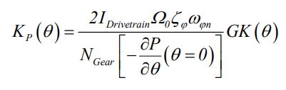
I think it may be that the modified Kp0 does not meet this formula(when GK=1,Kp(Theta)=Kp0)in your thesis and does not match the wind turbine information leading to problems.
So I would like to know how to modify the controller to change its response speed without modifying the wind turbine information?
Best regards,
Dear @He.Li ,
I’m not sure I understand everything that you are saying, but, the .f90 source code for the baseline DISCON controller of the NREL 5-MW baseline wind turbine uses PC_KI and PC_KP in place of the natural frequency. I would think if you want to change natural frequency, that you would change PC_KI and PC_KP accordingly. Perhaps the problem is that you only changed PC_KP?
Best regards,
Dear @Jason.Jonkman ,
As you said, I tried to modify PC_KP and PC_KI in equal proportions, but the calculated pitch Angle still did not converge.
The picture shows the part I modified.
(When I change PC_KP PC_KI back to the original value and re-generate the dll, the simulated pitch Angle will be in the normal range)

Best regards,
Dear @He.Li,
I don’t see that you’ve changed PC_KP and PC_KI consistently. You’ve decreased PC_KP by a factor of 1.57, which means PC_KI should be decreased by a factor of 1.57^2 = 2.46, but instead, of you’ve decreased PC_KI by a factor of 1.57.
Best regards,
Dear @Jason.Jonkman ,
You’re right, I forgot that the natural frequency in Ki is squared. I changed PC_KI to 0.000364223, But the results B1Pitch obtained are still not convergent.

Best regards,
Dear @He.Li,
Your solution appears to be unstable. What is happening at the beginning of the simulation? Are you initializing the rotor speed and blade-pitch angles to their expected (mean) values conditioned on mean hub-height wind speed? What natural frequency are you trying to slow the controller below? What are the time steps of your simulation?
Best regards,
Dear @Jason.Jonkman ,
The simulation I am working on is forced vibration through the ExtPtfm module.
for question (1), at the beginning, the warning shown in the figure appears

for question (2),I give a steady wind of 13m/s, I set
BlPitch to 5, RotSpeed to 12, PtfmSurge to 20 in ElastoDyn, which is same as when I used the unchanged controller.for question (3), I just want to change the speed of the blade pitch by modifying
PC_Kp and PC_Ki, for example, reduce PC_Kp to 0.004 and change Ki accordingly.for question (4),my previous time step was 0.01 seconds. After reading your reply, I tried to change it to 0.005 seconds, but the result was still unstable.
Best regards,
Dear @He.Li,
For the first question, can you share the results or plots of rotor speed, blade pitch, etc. from the start of the simulation? Is the blade pitch toggling between extremes from the start, or does it take a while to build to that?
Best regards,
Dear @Jason.Jonkman ,
Sorry, I need to clarify that the condition I am currently using to test the effect of the newly compiled controller is the wind-wave coupling condition with hydrodyn and moordyn on.
Below are the outputs of my Ptfmsurge, RotSpeed and B1pitch output,
B1pitch seems to have diverged at the start


Best regards,
Dear @He.Li,
I would guess the issue is that the RotSpeed is dropping quickly, but I’m not sure why it would do that. Is the generator torque controller enabled and have you changed it any way? Is AeroDyn enabled and set up properly? What wind speed are you applying?
Best regards,