Dear all,
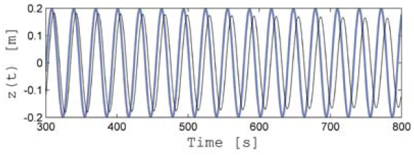
I have a question about one of the results from ‘Investigation of a FAST-Orcaflex coupling module for integrating turbine and mooring dynamics of offshore floating wind turbines’. I am trying to get same FAST result at figure 2 (simulation results for case I: free decay with z0=0.2 meters).
I found that tether damping is not present in FAST’s default setting, so I just put:
0.2 PtfmHeave for initial condition
0.0 PtfmCD for no damping
0.0 RdtnTMax for no damping
0 WaveMod
However, I got a result below:
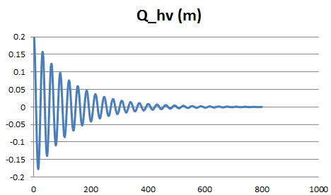
It looks like there is a damping effect. How can I get the result that looks like no damping? I used files of NRELOffshrBsline5MW_OC3Hywind.zip.
Sincerely,
Sungwon
Dear Sungwon,
Is this question for the coupled FAST+OrcaFlex simulation, or for the stand-alone FAST program? In any case, I’d make sure all avenues of damping are disabled (including aerodynamics, but this doesn’t appear to be the problem). You can try disabling individual DOFs except for heave. If the question is for the coupled FAST+OrcaFlex simulation, you will need to disable appropriate platform forces in the OrcaFlex vessel properties page. There is no link between the FAST platform input file and OrcaFlex, so different features need to be manually disabled. Lastly, check to make sure the line drag coefficient is zero. Let us know how this works out.
Thank you,
Marco
Thank you for your answering me Marco,
I am doing FAST only situation. I put 0.0 for air density, 0.0 for PtfmCD, 0.0 for RdtnTMax, and only used individual DOF for heave. However, the result shows the same shape above. I am trying to get the same graph as attached. Are there any other possible reasons or could you give me the input files and source code?
Thank you,
Sungwon
These aren’t the exact input files used in the paper you cited, but it should be enough to figure out where the discrepancy may rest. I quickly tested/simulated the system and saved figures in the ‘results’ folder. The heave response appears to be similar to the figure above. Let us know how this works out.
github.com/mmasciol/oc3
Thank you,
Marco
Thank you for giving me the input files. I have tried to run the FAST with the input files. I used the FAST and DISCON from NRELOffshrBsline5MW_OC3Hywind.zip file. However, I could not get the result you gave. I am thinking that there are some damping parts in source code. If you do not mind, can I get the source code?
Regards,
Sungwon
Could external (linear or quadratic) damping be applied to the system, similar to Eq. 4-10 here? nrel.gov/docs/fy10osti/47535.pdf
No additional external damping was applied to the system in Fig. 2. My guess is the executable you are using was specially compiled for the OC3 spar with linear damping. Instead, if you want to match the heave free-decay results in the paper, use FAST version 7.02.00d-bjj found here: wind.nrel.gov/designcodes/simulators/fast/.
Thank you,
Marco
My thinking is the same with you. I think that the executable has linear damping. I am a newbie using fortran, so it is very hard for me to compile new code. I am asking you to give me the source code and executable which you used. Could you send me them?
Many thanks!
Sungwon
I solved it with FAST v8.
Dear SungWon,
The FAST v7 executable provided with the OC3-Hywind model (here) includes the “additional linear damping” documented in: [url]http://www.nrel.gov/docs/fy10osti/47535.pdf[/url]. More information on this topic is provided in the following forum topic: Additional linear hydrodynamic damping in OC3 Hywind.
In FAST v8, it is easy to add (or remove) additional linear damping, additional quadratic damping, and additional linear stiffness directly through the HydroDyn input file, with no need to customize the source code.
Best regards,
Dear Jason,
I am working on a larger wind turbine (compared to NREL 5MW) mounted on a scaled-up OC4-semi submersible platform now. A divergence problem came up when I am trying to run the free-decay simulation for the global system.
Here is what we did:
We are trying to optimize the size of the platform to support the larger wind turbine properly and we first carried out the free-decay simulation to check the static stability of the new system. I studied the files that Marco had shared github.com/mmasciol/oc3 and created my own input files for my scaled up platform to run the free decay simulation (I mainly disabled the aerodyanamic loads, set wind speed=0.0, wave mode=0 and set initial heave motion to 0.2).
The simulation results for the 6 motions seem to be incorrect. Heave motion tends grows up to a very high “positive” value (~ 85m) i.e. the platform is tending to rise up above the MSL to height of 85m. Also the surge motion does not seem to converge. Please find attached the figures for surge and heave motions.
Do you know happen to know a particular reason for this behavior?
Any help is highly appreciated.
Regards,
Jinsong
Dear Jinsong,
I’m assuming you are using the latest release of FAST (v8.10) for your analysis?
It is difficult to know what exactly is causing your problem based on the information you’ve provided, but at the very least a floating system model should be set up so that external buoyancy from displaced water balances with the weight of the system (including the weight of the rotor-nacelle assembly, tower and substructure) and mooring system pretension as described in Section 6.8.1 of the HydroDyn User’s Guide and Theory Manual: nwtc.nrel.gov/system/files/Hydr … nual_0.pdf. Has you model been set up as described in that section?
Best regards,
Dear Jason,
Thanks for your prompt reply. The document you provided is really helpful!
I am using FAST V8.09 for my work,not the latest one. I will check with the latest version(V8.10) later to see if there is any difference.
I go through the HydroDyn manual and double checked my model. In summary, here are what I did to build this scaled up platform model (λ is the scaling factor):
- Scaled up the platform geometry model in Multi-surf in x,y,z directions by factor λ
- In ElastoDyn input file, scaled up the platform mass by λ^3 and inertia by λ^5. PtfmCMzt scaled by λ. To avoid double calculating teh restoring terms in WAMIT, the VCG in WAMIT is set to be 0. Then run WAMIT to get the hydrodynamic coefficients and excitation forces (.1,.3 and.hst) with wave frequency range from 0.02 ran/sec to 5 rad/sec
- In HydroDyn input file, change PtfmVol0 according to WAMIT output and set PtfmCOBxt=PFtmCOByt=0. And also member outer diameter, PropD are scaled up by λ, however the thickness of the members are assumed to be same as OC4-Semi. FillFSLoc is also scaled up by λ.
- AddCLin for terms (4,4) and (5,5) are scaled up by λ^4
The assumptions made in my work is that both transverse and axial hydrodynamic coefficients for viscous drag, added mass, and dynamic pressure Modifications are assumed to be same as OC4-DeepCwind. And also neither 2nd order wave nor current are considered in my study.
With all the work done above, I run the simulation again and the results are still the same as I posted before. I checked the HydroDyn summary file and compared it with OC4-Semi HydroDyn summary file, all the volume terms and buoyancy terms are reasonable based on the scaling factor except the internal BuoyMyi term, which is caused by filled members (ballast water). For OC4-Semi it is 3.051758E+02(N-M), mine -1.068115E+04 (N-M).(λ =1.5 for this case).
I am not sure if this will cause my trouble. But if it was, I think of two terms that are related to internal buoyancy, 1. the size of the side columns and FillFSLoc, which are scaled up by λ. 2: the term AddCLin as you discussed in the topic AddCLin for OC4 Semisubmersible, it is added because of the ballast water. Does the scaling method I used for these parameters make sense?
If the BouyMyi is not a problem, what else can cause this problem in your perspective? Any suggestions would be greatly appreciated!
The attached is the HydroDyn summary file for both OC4DeepCwind and the scaled up model.
Regards,
Jinsong
Dear Jinsong,
Your scaling approach makes sense to me. Have you also scaled the geometry in ElastoDyn and the mooring properties in MAP?
I doubt the difference in the BuoyMyi as output in the HydroDyn summary file is the cause of any problems. In reality, this term should be zero because the ballast is balanced about yt. It is likely nonzero due to numerical round-off in the internal calculation. However, the nonzero residuals that remain are likely very small relative to other pitching moments in the system.
I always find it useful to simplify the model in a debugging process. I would start by enabling only the platform-heave DOF in a simulation with still water.
Best regards,
Dear all,
I have a question about the results I got from FAST to compare with those from experimental test, concerning a spar buoy.
I am trying to get FAST result as in the experimental free decay test for surge oscillation, as shown in the figure here attached.
I put PtfmSurge for initial condition, set rotor rotation as 0, disabled all control inputs.
Please, could someone suggest me which parameters in FAST should I modify in order to reach a similar result with the experiment in terms of surge?
Thank you very much in advance
Best regards,
Luigia
Dear Luigia,
Here are a few things I see:
- You should set the same initial conditions as the experimental data e.g. set PtfmSurge in the ElastoDyn input file be to closer to 5 m.
- It appears that the surge natural frequency in FAST is a bit different than the experiment. This suggests a bit different surge stiffness or surge added mass (my guess is the mooring stiffness is the most likely culprit).
- It appears that surge damping in FAST is a bit different than the experiment e.g. you may need to play with the hydrodynamic damping/drag coefficients.
I hope that helps.
Best regards,
Hello Jason,
I have a similar problem as Luigia. I have done free decay tests with the OC3 Hywind model in FAST and Bladed without air or waves. In Bladed it seems to me that there is a shift in natural frequency’s.
In Bladed I am using the MooringLineFD.txt you provided in the forum for the three default mooring lines ( Fx(deltax) and Fz(deltax)).
Also I added linear damping for Heave and Yaw, as well as additional stiffness for Yaw. (Heave and Yaw Free Decay are matching good).
Next I added linear damping in Sway direction. All values are used as mentioned in “Definition of the Floating System
for Phase IV of OC3”.
I excluded the damping in Surge direction, because with it the amplitudes in the Surge Free Decay were getting smaller to fast.
Also additional stiffness were not included (roll-roll, pitch-pitch and heave) because with them the problem got worse as frequency went up.
Mass and Inertias are matching.
The mooring Lines are attached at (-70/5.2/0), (-70/-2.6/4.5) and (-70/-2.6/-4.5) at the platform.
Do you have any idea what could cause this differences?
Best regards,
Simon
Dear Simon,
I’m not really sure I can comment as to why your response from Bladed differs from that of FAST. Just a few comments:
- The MooringLineFD.txt file we provided only considers variations in mooring tension due to horizontal motion of the fairlead (for 3 lines in 3D, this would equate to variations in surge, sway, and yaw). This file does not consider variations in mooring tension due to variations in heave, roll, or pitch motion, which may lead to differences when heave, roll, and/or pitch motions are significant.
- It seems odd to me that you’d have to exclude the additional surge damping to get better results. This suggests to me that there is something fundamentally different between the FAST and Bladed models, but I’m not sure what that might be.
- By the additional stiffness in heave, roll, and pitch, I’m assuming you are referring to the hydrostatic restoring terms? Perhaps these terms are accounted for elsewhere in Bladed?
- You mentation that the fairlead locations are (-70/5.2/0), (-70/-2.6/4.5) and (-70/-2.6/-4.5). I’m not familiar with the Bladed coordinate systems, but according to the coordinate system shown in Figure 3-1 of the OC3-Hywind specifications report, the fairlead locations should be at (5.2/0/-70), (-2.6/4.5/-70) and (-2.6/-4.5/-70).
I suggest that you contact Bladed technical support for further help.
Best regards,
Dear Jason,
• But in OC3 only these values for delta_x where used? (For the codes that needed this type of input)
• Yes I agree.
• There is no option to define “hydrostatic restoring terms” in Bladed 4.4. The only possibility I can see is to use the mooring model to include this values as this model is only an extended onshore-foundation module that has been modified to incorporate mooring line weight and the coordinate system is changed. For the Yaw and Heave DOF this approach worked quit well.
• I gave the coordinates as (z/x/y) with origin at SWL in tower centerline with z upwards, x downwind and y as right handed system.
I’ll try to get info from DNV GL, but as I am using a license without support agreement I am not that optimistic.
Best regards,
Simon
Dear Simon,
I’m not aware of which tools in the OC3 project used the data from MooringLineFD.txt files; I just wanted you to be aware of the potential limitation using that data.
Best regards,
Hello everyone,
I solved the problem and want to point out where my error was:
In Bladed the Hydrodynamic Added Mass Coefficient has to be set to 1+“the value used in FAST”. As for OC3 Phase IV this coefficient is defined to 0.969954 I thought that it would be reasonable to use 1 in Bladed as it gave errors with values smaller than 1.
With 1.969954 defined the response for surge free decay is in agreement with FAST.
Also Jason was right, that it is strange, that I had to exclude additional damping and stiffness to get better results. After correcting added mass and setting all additional values as stated in OC3 the response agreed well.
But, and that’s my question, I had to define the additional hydrostatic stiffness for roll-roll and pitch-pitch to 10% of the advised value (so -499,918,000 nm/rad and not -4,999,180,000 nm/rad)
As a single negative value was not accepted I calculated values that define the torque for a specific angel of deflection (-499,918,000/rad = Nm).
So I got a linear graph with torque over angel. These values were used in lookup tables in Bladed.
Also I excluded the additional stiffness for heave as it leads to too small responses even when combined with the advised -4,999,180,000 Nm/rad.
In the FAST models I have excluded the additional hydrostatic stiffness as there is potential flow used and not only Morison-equation as in Bladed 4.4.
Can anyone report, that the value printed in NREL/TP-500-47535 (Definition of the Floating System for Phase IV of OC3) on page 13 is exact?
Best regards,
Simon


