Discussion on tower foundation load under extreme working conditions

Dear,
I used an IEA15MW semi submersible wind turbine for simulation, and the configuration was completely set according to Task 37. I have doubts about the value of the tower base load in the x-direction. Below is my operating condition table.


Below is my extreme value statistics on tower foundation loads


My wind, waves, and current directions are all 0 degrees. In theory, the bending moment of the side to side tower foundation under DLC10 working conditions makes me wonder why there is such a large value. In theory, the before aft should be greater than the side to side direction. I thought that the only force that affects the side to side direction is the wind. My wind file was generated using Turbsim for EWM50year, and below are the wind speed time domain diagrams for the three directions

As you can see, there is no problem with the wind speed in the y direction. So, what is the reason for the large bending moment of the tower base in the side to side direction in dlc10?
I hope to receive everyone’s help!
Best regards,

Dear @Yushun.Fu,

Can you clarify how you are setting up dlc10? Presumably you are modeling an idling rotor with the generator disabled, the blade-pitch angles feathered, and simplified aerodynamics without BEM and unsteady airfoil aerodynamics disabled? Do you have a nacelle-yaw error? What is happening with platform yaw?

Not sure this matters to your question, but what is meant in your figure regarding QS, LM1 and LM2?

Best regards,

Thank you for your reply.
1.My dlc10 settings are as follows:

---------------------- FEATURE SWITCHES AND FLAGS ------------------------------ 
      1   CompElast       - Compute structural dynamics (switch) {1=ElastoDyn; 2=ElastoDyn + BeamDyn for blades}  
      1   CompInflow      - Compute inflow wind velocities (switch) {0=still air; 1=InflowWind; 2=external from OpenFOAM} 
      2   CompAero        - Compute aerodynamic loads (switch) {0=None; 1=AeroDyn v14; 2=AeroDyn v15} 
      1   CompServo       - Compute control and electrical-drive dynamics (switch) {0=None; 1=ServoDyn} 
      1   CompHydro       - Compute hydrodynamic loads (switch) {0=None; 1=HydroDyn} 
      0   CompSub         - Compute sub-structural dynamics (switch) {0=None; 1=SubDyn; 2=External Platform MCKF}
      3   CompMooring     - Compute mooring system (switch) {0=None; 1=MAP++; 2=FEAMooring; 3=MoorDyn; 4=OrcaFlex} 
      0   CompIce         - Compute ice loads (switch) {0=None; 1=IceFloe; 2=IceDyn} 
      0   MHK             - MHK turbine type (switch) {0=Not an MHK turbine; 1=Fixed MHK turbine; 2=Floating MHK turbine}
---------------------- DEGREES OF FREEDOM --------------------------------------
True          FlapDOF1    - First flapwise blade mode DOF (flag)
True          FlapDOF2    - Second flapwise blade mode DOF (flag)
True          EdgeDOF     - First edgewise blade mode DOF (flag)
False         TeetDOF     - Rotor-teeter DOF (flag) [unused for 3 blades]
False         DrTrDOF     - Drivetrain rotational-flexibility DOF (flag)
False          GenDOF      - Generator DOF (flag)
False         YawDOF      - Yaw DOF (flag)
True          TwFADOF1    - First fore-aft tower bending-mode DOF (flag)
True          TwFADOF2    - Second fore-aft tower bending-mode DOF (flag)
True          TwSSDOF1    - First side-to-side tower bending-mode DOF (flag)
True          TwSSDOF2    - Second side-to-side tower bending-mode DOF (flag)
True          PtfmSgDOF   - Platform horizontal surge translation DOF (flag)
True          PtfmSwDOF   - Platform horizontal sway translation DOF (flag)
True          PtfmHvDOF   - Platform vertical heave translation DOF (flag)
True          PtfmRDOF    - Platform roll tilt rotation DOF (flag)
True          PtfmPDOF    - Platform pitch tilt rotation DOF (flag)
True          PtfmYDOF    - Platform yaw rotation DOF (flag)
---------------------- INITIAL CONDITIONS --------------------------------------
          0   OoPDefl     - Initial out-of-plane blade-tip displacement (meters)
          0   IPDefl      - Initial in-plane blade-tip deflection (meters)
          90  BlPitch(1)  - Blade 1 initial pitch (degrees)
          90  BlPitch(2)  - Blade 2 initial pitch (degrees)
          90  BlPitch(3)  - Blade 3 initial pitch (degrees) [unused for 2 blades]
          0   TeetDefl    - Initial or fixed teeter angle (degrees) [unused for 3 blades]
          0   Azimuth     - Initial azimuth angle for blade 1 (degrees)
          0   RotSpeed    - Initial or fixed rotor speed (rpm)
          0   NacYaw      - Initial or fixed nacelle-yaw angle (degrees)
---------------------- PITCH CONTROL -------------------------------------------
0                      PCMode      - Pitch control mode {0: none, 3: user-defined from routine PitchCntrl, 4: user-defined from Simulink/Labview, 5: user-defined from Bladed-style DLL} (switch)
0.0                    TPCOn       - Time to enable active pitch control (s) [unused when PCMode=0]
---------------------- GENERATOR AND TORQUE CONTROL ----------------------------
0                      VSContrl    - Variable-speed control mode {0: none, 1: simple VS, 3: user-defined from routine UserVSCont, 4: user-defined from Simulink/Labview, 5: user-defined from Bladed-style DLL} (switch)
1                      GenModel    - Generator model {1: simple, 2: Thevenin, 3: user-defined from routine UserGen} (switch) [used only when VSContrl=0]

I will set PCmode to 5 and VScontrol to 5 except for shutdown conditions

======  General Options  ============================================================================
False                  Echo        - Echo the input to "<rootname>.AD.ech"?  (flag)
default                DTAero      - Time interval for aerodynamic calculations {or "default"} (s)
0                      WakeMod     - Type of wake/induction model (switch) {0=none, 1=BEMT, 2=DBEMT, 3=OLAF} [WakeMod cannot be 2 or 3 when linearizing]
1                      AFAeroMod   - Type of blade airfoil aerodynamics model (switch) {1=steady model, 2=Beddoes-Leishman unsteady model} [AFAeroMod must be 1 when linearizing]

Except for shutdown conditions, I will set WakeMod to 1 and AFAeroMod to 2

2.The following figure shows the time-domain diagram of Yaw direction motion on my platform


3.As you can see, I did not encounter any errors while running the DLC10 operating condition. In order to make it clear, I have added NacYaw

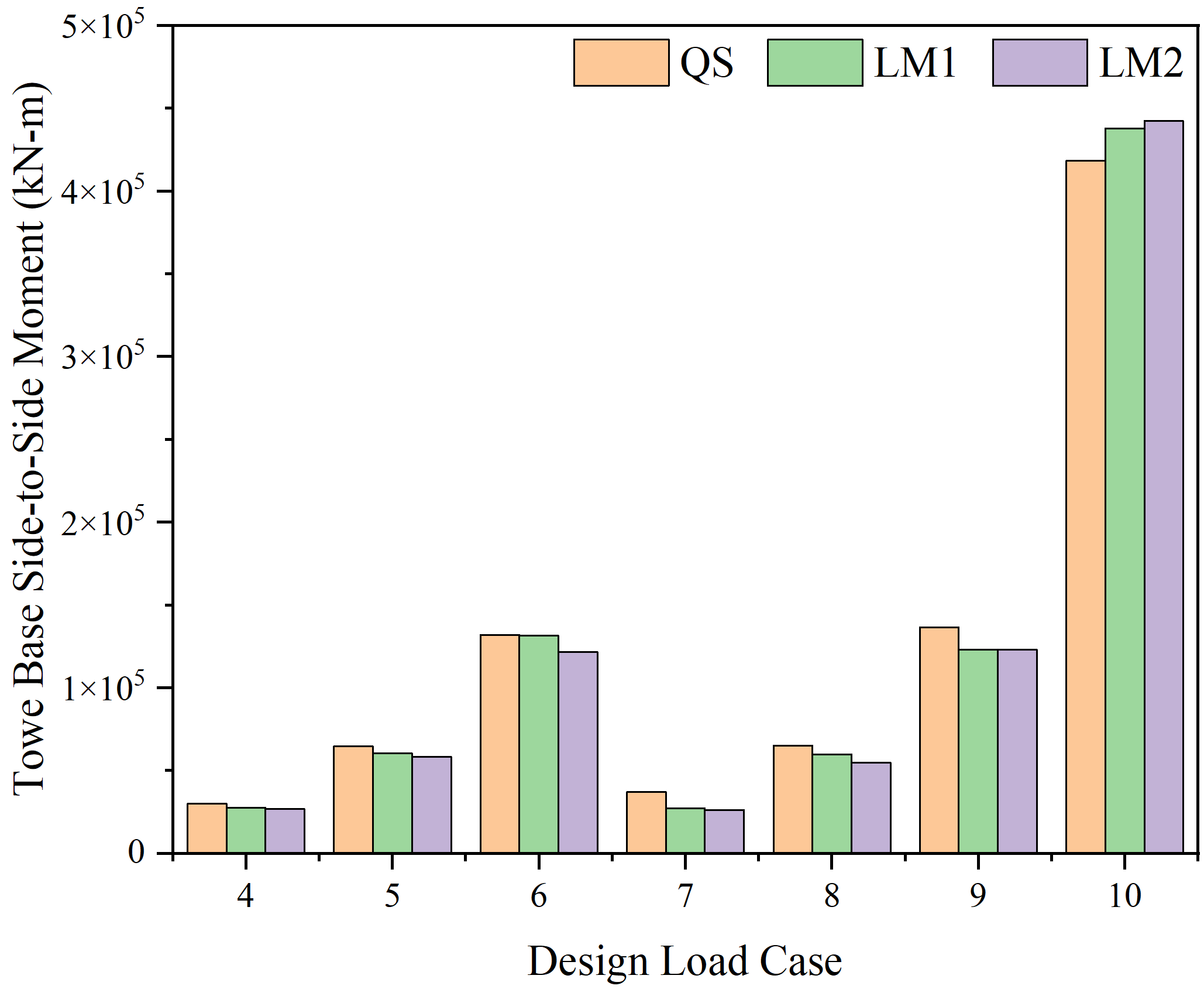
4.My QS refers to the use of MAP++quasi-static, LM1 uses MoorDyn to lumped mass, and LM2 adds Water Kinematics file on the basis of LM1

We look forward to your reply!
Best regards,

Dear @Yushun.Fu,

Thanks for clarifying. Just a few comments:

  • During parked or idling condition under storm conditions, I would expect the aerodynamic loads on the rotor to be quite small, unless the yaw error becomes sizeable. There are likely sizeable yaw errors under the turbulent inflow and platform-yaw motion you are seeing, but you can quantify how large by outputting the yaw error via AeroDyn output RtSkew.
  • Do you have tower aerodynamic loads enabled in AeroDyn (TwrAero = TRUE), which I would expect to dominate over rotor aerodynamic loads when the yaw error is not sizeable?
  • I see that you’ve parked the rotor rather than kept the rotor idling. Normally a brake would only be applied for such a large wind turbine during maintenance operations. I would suggest idling the rotor by setting GenDOF = TRUE in ElastoDyn with GenTiStr = TRUE and TimGenOn > TMax in ServoDyn.

Best regards,

Dear @Jason.Jonkman

I am also interested in the setting of the wind turbine under storm conditions, and I would like to know how the YawDOF should be set up?

I would also like to know the parked position of the blades. How can I view the initial parked position of the blades in the model? And how can I view the change in blade position during idling?

Best regards,
Jundong

Dear @Jundong.Wang,

I’m not sure I really understand your questions; just a few comments:

  • It is much more common for utility-scale wind turbines to be idling under storm conditions than parked with a brake, which is typically only deployed for maintenance purposes.
  • Just like in operational cases, the YawDOF can be enabled under storm conditions if you want the yaw actuator to be enabled or disabled if you don’t. Regardless, it is common to keep the nacelle-yaw angle fixed in position (with or without YawDOF enabled) for a given simulation.
  • The initial rotor (blade) orientation in OpenFAST is determined by ElastoDyn input Azimuth and you can track the change in orientation of an idling rotor through the ElastoDyn output Azimuth.

Best regards,

Dear @Jason.Jonkman
When I attempted to operate the turbine at high wind speeds, I observed that the thrust of the turbine was negative, but the power generation was normal. What could this situation be related to? I’m not sure if this is normal; the phenomenon I observed is that Rotor thrust has a correlation with the inflow angle.

LC#1 & LC#3 correspond to high wind speed. LC#2 is normal wind speed.

Best regards,

Dear @Jundong.Wang,

Above rated wind speed in a conventional wind turbine with variable speed and active blade pitch-to-feather control, the blade-pitch angle will increase with mean wind speed, reducing rotor thrust. At a high enough wind speed, the blades will have pitched high enough that the thrust will reverse sign on parts of the blade. That said, normally a wind turbine is not operated at such a high mean wind speed. Rather, a wind turbine normally shuts down at around 25 m/s.

Please note that–as has been discussed in other topics on this forum–you are plotting ElastoDyn output RotThrust, which is the reaction force along the shaft, which not only includes the aerodynamic thrust, but also weight and inertial terms.

Best regards,

Dear @Jason.Jonkman
I am trying to analyze the performance of the tower top displacement under different load conditions. Therefore, I conducted a PSD analysis, and the code is as follows:

% ============= tower for-aft analysis
% read TTDspFA  
TTDspFA1 = A1p(48001:end-1, 36);  
TTDspFA2 = A2p(48001:end-1, 36);  
TTDspFA3 = A3p(48001:end-1, 36);  

% Remove mean from data
TTDspFA1f = TTDspFA1 - mean(TTDspFA1);
TTDspFA2f = TTDspFA2 - mean(TTDspFA2);
TTDspFA3f = TTDspFA3 - mean(TTDspFA3);

% FFT settings  
nfft = 2^15;               % Number of FFT points  
Fs = 80;                   % Sample rate  
df = Fs/nfft;              % FFT frequency resolution  
noverlap = 0;              % Percent overlap  
fwin = flattopwin(nfft);   % Flattop - good for monochromatic signals where amplitude accuracy is required  
CG = sum(fwin)/nfft;  
NG = sum(fwin.^2)/nfft;  

PxxS1 = pwelch(TTDspFA1f,fwin,noverlap,nfft,Fs,'onesided'); %Scaled Power Spectral Density (PSD), m^2/Hz
PTTDspFA1f = PxxS1*NG/CG^2;                                        %Power Spectral Density (PSD), m^2/Hz 
fTTDspFA1f = Fs/2*linspace(0,1,nfft/2+1);

PxxS2 = pwelch(TTDspFA2f,fwin,noverlap,nfft,Fs,'onesided'); %Scaled Power Spectral Density (PSD), m^2/Hz
PTTDspFA2f = PxxS2*NG/CG^2;                                        %Power Spectral Density (PSD), m^2/Hz 
fTTDspFA2f = Fs/2*linspace(0,1,nfft/2+1);

PxxS3 = pwelch(TTDspFA3f,fwin,noverlap,nfft,Fs,'onesided'); %Scaled Power Spectral Density (PSD), m^2/Hz
PTTDspFA3f = PxxS3*NG/CG^2;                                        %Power Spectral Density (PSD), m^2/Hz 
fTTDspFA3f = Fs/2*linspace(0,1,nfft/2+1);

However, I cannot be sure what several spectral peaks represent. I found the natural frequencies of different parts in https://www.nrel.gov/docs/fy09osti/38060.pdf, but there doesn’t seem to be a correspondence.


I conducted time domain analysis , and theoretically, the frequency of the 1st Tower Fore-Aft should be observable from the PSD analysis.

Is my PSD analysis incorrect, or do the spectral peaks of the PSD represent other meanings?

Best regards,
Junius.

Dear @Jundong.Wang,

I am Riad, a wind turbine enthusiast.

I cannot comment on the values of the natural frequencies you have found the document. Nonethless, for the PSDs you present, it is not obvious that you will find the tower natural frequencies in the PSDs since you are simulating real wind and wave loads. Maybe aerodynamic damping or other phenomenon can highly impact your response.

However, when you run a free decay test you should obtain the natural frequencies of each mode.

Best regards,

Riad

Dear @Jundong.Wang,

I’m not familiar with all of your MATLAB calculations, but are you tying the frequency step to the simulation length? You could try comparing your calculations to the simple Jason_PSD.m script shared on this forum before: User defined spectrum from routine UserWaveSpctrm in HydroDYn - #7 by Jason.Jonkman.

Like @Riad.Elhamoud, I’d say that the tower fore-aft mode is often heavily damped aerodynamically, making its natural frequencies difficult to spot. What you are more likely to see in the tower fore-aft signal is the rotor speed (1P) and its harmonics (3P, 6P, etc.) as the rotor spins through full-field turbulence.

Best regards,

Dear @Jason.Jonkman @Riad.Elhamoud

Thanks for your kind help!

Best regards,
Junius