Hi all,
I have been trying to replicate the strain calculation in WISDEM using the equations listed in RotorSE ComputeStrains
        x, y = rotate(xuu, yuu)
        strainU = M1 / EI11 * y - M2 / EI22 * x - F3in / EA

        x, y = rotate(xll, yll)
        strainL = M1 / EI11 * y - M2 / EI22 * x - F3in / EA
I ran the IEA 15MW turbine as is with no changes in WISDEM. Then from the WISDEM output, I used the following variables to try replicating WISDEM’s output for strain:
rotorse.rs.strains.alpha
rotorse.rs.strains.EI11
rotorse.rs.strains.EI22
rotorse.rs.strains.M1
rotorse.rs.strains.M2
rotorse.rs.strains.F3
rotorse.xu_spar
rotorse.xl_spar
rotorse.yu_spar
rotorse.yl_spar
rotorse.xu_te
rotorse.xl_te
rotorse.yu_te
rotorse.yl_te
All position vectors were rotated to align to the principal axes.
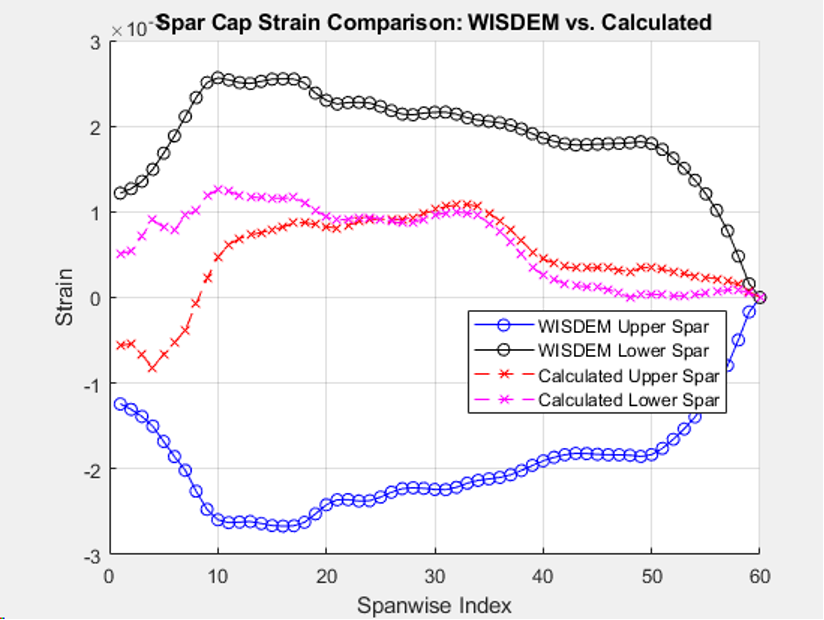
However, my resulting strains did not match WISDEM, and were quite a bit off from one another. I am pretty sure I replicated these equations. This plot just shows the spar caps, but I saw differences in the trailing edge strains as well. Does anyone have any ideas why this would be the case?
Thanks in advance
There are some coordinate transformations necessary when computing strains. Take a look at the source code for the calculation here and hopefully that clarifies where the mismatch might be.
Hi Garrett,
Thank you for your response. I did rotate the coordinates according to the source code in my calculation. I believe WISDEM’s default used pbeam set to false, so no rotation of M1 or M2 was necessary. I did try rotating them just to check and still got differing results. Is there anything else I could try?
Also, I noticed that the axial component in the source code is negative but the documentation has it as positive as I would expect. This doesn’t change the results much regardless since the axial component is much smaller but I was curious about that as well.
Thanks again,
Max
Hi Everyone,
Danu has been posting on my behalf since I was having issues with my forum account creation that has since been resolved. Has there been any update on this topic? I still have not noticed any glaring differences between my approach and that of the source code.
x_u_spar_p = cosd(alpha) .* xu_spar + sind(alpha) .* yu_spar;
y_u_spar_p = -sind(alpha) .* xu_spar + cosd(alpha) .* yu_spar;
strainU_spar_calc = M1 ./ EI11 .* y_u_spar_p - M2 ./ EI22 .* x_u_spar_p + N ./ EA;
here is an example of the MATLAB code I have been using for the upper spar cap in my calculations. Thanks again.
Best,
Max