I am using Airfoil prep for the first time and have a couple of questions. How do I determine “Cn at stall angle for negative Angle of Attack”? Also how is Aspect Ration (AR) calculated for this? Since this is for a variable speed machine do I select rpm based on the RE number for the airfoil data I am working with? I will attach my modified Airfoil prep spreadsheet and would appreciate feedback if anyone would be so kind as to take a look at it. I have linked the worksheets to save time.
Thanks for any input,
AirfoilPrep144re099.xls (447 KB)
Dear Robert,
An aerodynamicist could probably offer better advice, but I’ll give you my two cents.
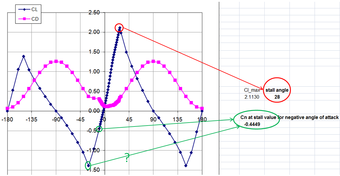
The “Cn at stall for negative angle of attack” needed in the DynStall worksheet can be obtained through visualization in the Cn plot given in the worksheet.
The Aspect Ratio needed in the TableExtrap worksheet should be calculated as the ratio of the blade length to a “typical” chordlength, say the chordlength at 75% span.
Ideally, one would use airfoil tables spanning multiple Reynolds numbers or at least assess the influence of Reynolds number on the airfoil data over the range of interest. What is more common is to choose a “representative” Reynolds number based, say, on the rated rotor speed.
Best regards,
Hello,
I’m a french M.Sc. Student in internship in Mexico in a laboratory of engineering of coastal processes (LIPC, UNAM) to investigate the wind potential in the Yucatan peninsula. We have build a little home-made wind turbine of approximately 500W (diam=3.2m) that will be soon installed in front of the see of the gulf of Mexico.
I have to determine the aerodynamic performances of that rotor (Cp, power curves in function of the wind speed velocity with WT_Perf) which is unique and doesn’t correspond to any rotor known.
I have used XFoil (Xflr5) code to generate Cd-Cl tables on [-10°,30°], and know I use the “AirfoilPrep.xls” program. I have read all the threads about “AirfoilPrep”, but I am not sure having exactly understood the following parameters “Stall angle” and “Cn at stall value for negative angle of attack”.
Could anyone check these 2 parameters on the 3 different curves (corresponding to 3 profiles of my home-made blade) generated by the “TableExtrap” sheet (see attached)?
And my question referring to these parameters is: do I have to choose “Stall angle” and “Cn at stall value for negative angle of attack” only on the range of value I have generated with help of XFoil (as I chose it), or could I choose for example a “Cn at stall value for negative angle of attack” belonging to the values generated by the extrapolation of AirfoilPrep (See the 2 first curves attached to understand)
I hope I was quite clear, and sorry for my approximate English.
Thank you for your help
Sincerly
Clément
PS: the Reynolds numbers are equals to 50,000


Dear Clément,
Those parameters (Stall Angle, etc.) near the top of the airfoil files are for compatibility with the Beddoes-Leishman dynamic stall model in AeroDyn. If you are only using the files with WT_Perf, you can just put in zeroes for the values, but the lines must be there. If you would like to know more about the stall parameters, please see the AeroDyn User’s Guide that is available on the AeroDyn web page.
Marshall
Hello
I don’t have enough data to extrapolate to get the significant wave height or other data with a recurrence period of 20 yr. Now I set the mean wind speed to 22m/s. With FAST, I get 20 outputfiles based on 20 different random numbers. I want to extrapolate to get Tower Top Fore-Aft Displacement, Tower Base Fore-Aft Bending Moment and other data with a recurrence period of 20 yr. Do it right? Someone extrapolated to get out-of-Plane Root Bending Moment in this way. May I extrapolate to get Tower Top Fore-Aft Displacement or Rotor Speed using this method? OR I JUST need calculate only once with FAST to get the Tower Top Fore-Aft Displacement and Rotor Speed ? Thank You.
Dear Yiqing,
I think this question should belong in a different forum topic (it has nothing to do with AirfoilPrep).
Regardless, the IEC 61400-1 design standard explains how an aeroelastic code can be used for loads extrapolation to calcalate the fatigue damage of wind turbine components over a 20-yr lifetime. Indeed, you need to know the mean wind speed distribution at hub height, the turbulence class, and the results from a range of simulations from cut-in to cut-out wind speed.
Best regards,