Dear Gabriele,
The big items missing from a strip-theory-only solution that are included in a hybrid model combining strip theory and potential flow is the inclusion of diffraction and radiation damping in the latter. I would expect both of these effects to be quite minimal in the OC3-Hywind spar buoy, so, I would expect only small differences between the strip-theory-only and hybrid solutions. Of course, the devil is in the details regarding how the strip-theory model is set up e.g. is the discretization set to obtain a converged solution? are the hydrodynamic coefficients set consistently between both models?, etc.
Best regards,
Dear Dr. Jonkman,
as always you are very kind to answer me.
I get what you are saying.
I took the hybrid model and modified only the AddClin matrix as reported in Hydrodyn guide, but I also need to calibrate the model.
After what you said I suppose that I have to make several discretization attempts to find a converge solution, and also to modify the hydrodynamic coefficients? How I can check that “the hydrodynamic coefficients set consistently between both models?”
What parameters do you suggest to control to check the convergence?
I really appreciate your support. Thank you.
Kind regards,
Gabriele
Dear Gabriele,
The OC3-Hywind specifications document recommends setting the added-mass coefficient to 0.969954 in the strip-theory solution to match the surge added-mass of the potential-flow solution: nrel.gov/docs/fy10osti/47535.pdf. I haven’t checked, but this may not yield a perfect result for platform-pitch. You could vary the added mass with depth to match both. You could also set the axial added-mass-coefficients to get the proper added mass in heave.
You can change the number of strip-theory members to study the convergence of the solution.
Best regards,
Dear Dr. Jonkman,
you obtained the Added Mass coefficient to match the surge response comparing the zero frequency limit of A11 (found in the .1 file right?).
It is possible to follow a similar procedure for the other responses, for example for the heave as you suggested me to “set the axial added-mass-coefficients to get the proper added mass in heave” ?
Thank you very much.
Best regards,
Gabriele
Dear Gabriele,
Yes, but it will be a little trickier for heave and pitch. This is because the heave added mass will come both from the tapered region of the spar and the free-end of the spar at its bottom. And the pitch added mass depends on the distribution of transverse added mass along the spar.
Best regards,
Dear Dr. Jonkman,
I was comparing the Hybrid/strip-theory response for an extreme irregular sea (H=15m, T=19s) with no wind.
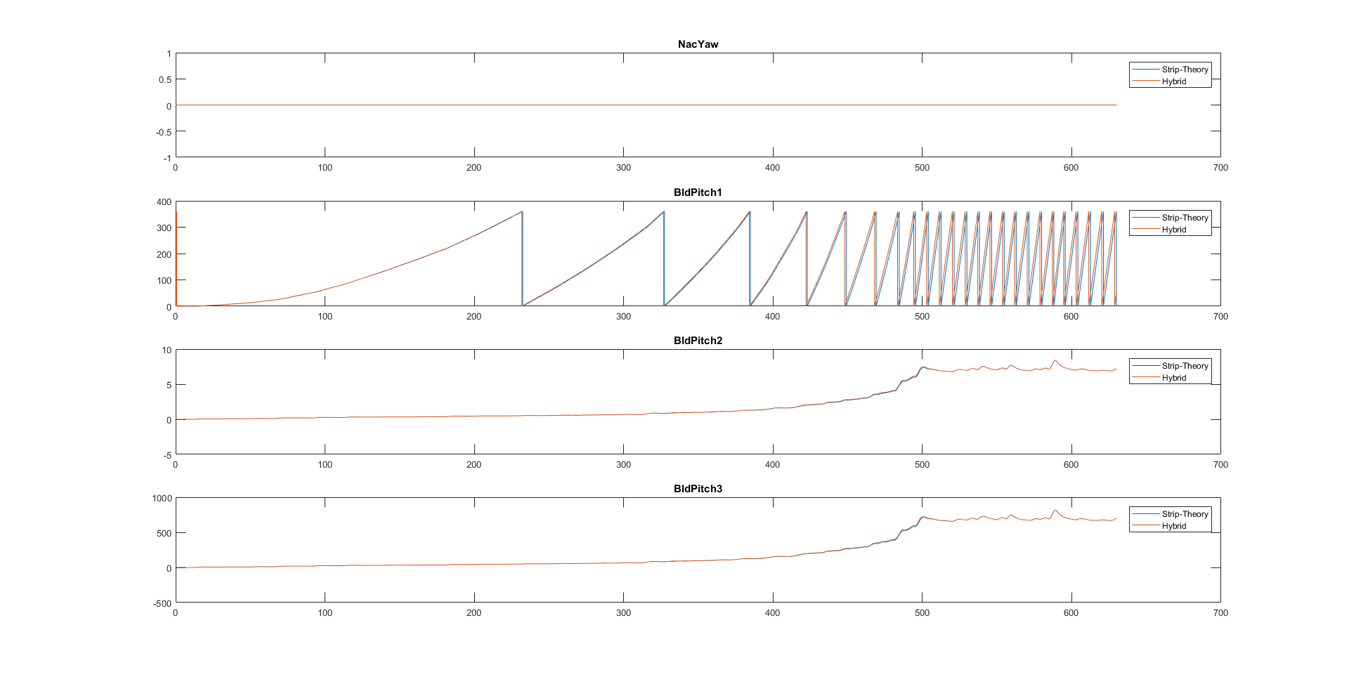
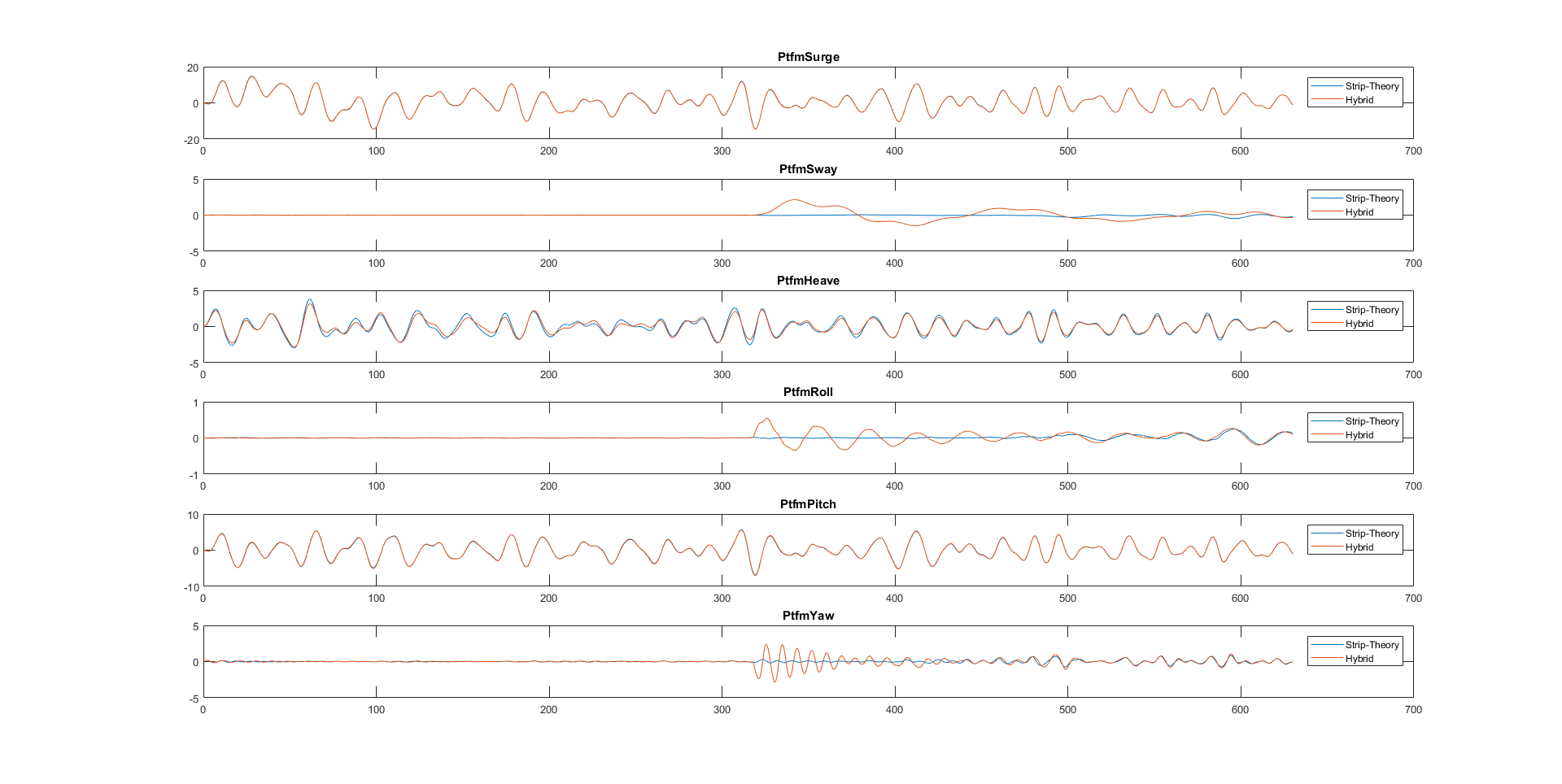
In this simulation something strange happened for the Hybrid solution. Please see the images attached. Do you have any idea why this happen?
It is strange that the rotor started to run, and also the blade pitch angles are very anomalous. This is might be the beginning of the strange platform motions that starts at 300 s.
I the simulation with a calm sea (H=1.4, T=6.5s) this didn’t happen.
For the simulation I set:
- CompInflow=0
- CompAero=2
- CompServo=1
- Wakemod=0
- AFAeromod=2
Thank you.
Kind regards,
Gabriele
Dear Gabriele,
I only looked briefly at your results. Your plot of BldPitch1 looks more like a rotor azimuth angle for a rotor that is accelerating; are you sure you’ve labeled this plot correctly?
Regardless, you have AeroDyn enabled without InflowWind, which is a bit odd (AeroDyn will still have some relative wind velocity due to the motion of the structure). I’d probably disable AeroDyn when disabling InflowWind.
Best regards,
Dear Dr. Jonkman,
regarding the Aerodyn solutor with no wind I read in a post that if I want to model the turbine in the vacuum I should disable Aerodyn. Instead if I would want to model it in still air (so with air resistance if the tower in moving) I should set the Aerodyn solutor on. Is it right?
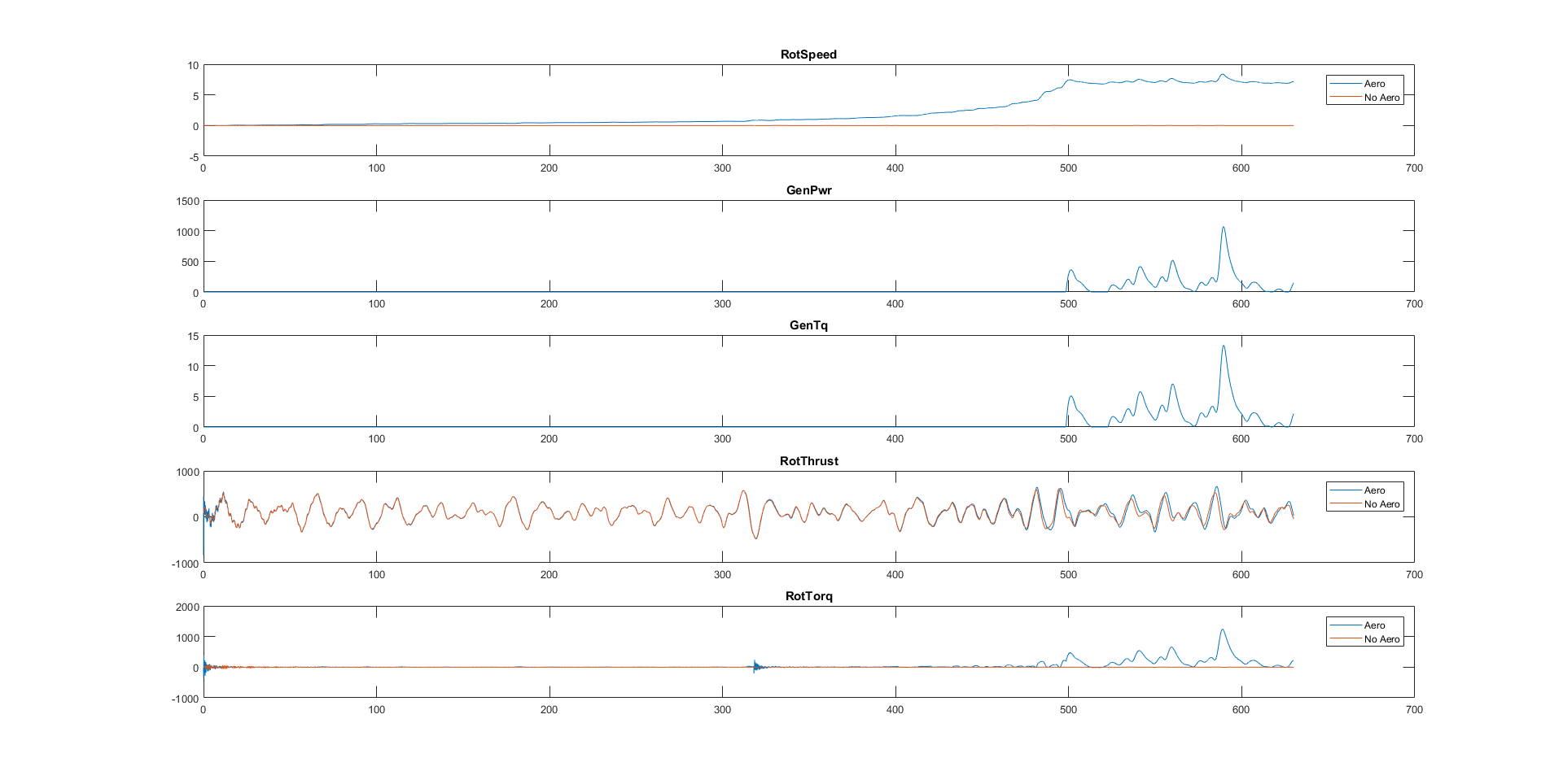
Anyway I ran also a simulation comparing the solution if Aeordyn is on or off, and the results show always with that instabilty. I disabled also the Servdyn but the solution still remain very strange; at around 300s an instability always appears in all the models. In the case where Aerodyn is off it is less pronouceate, but it is still present.
In this study I am modelling a Hywind Wind Turbine with no wind, irregular sea (H=15m, T=19s) with the wave Hybrid solutor.
I started this solution because of in the previous comparison (strip-theory vs. hybrid with extreme sea state) the same strange behaviour appeared.
With the calm sea state (H=1.4m, T=6.5s) this instability doesn’t appear at all.
Please see in the attachment a folder in which you can find the comparison graphs and also the inputs file and the Hydrodyn file.
Thank you for your help.
Best regards,
Gabriele
Comparison.zip (482 KB)
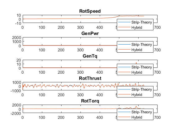
I attach also this graph if it might be useful.
Thank you,
Gabriele
Dear Gabriele,
Yes, you can model aerodynamics in still air by enabling AeroDyn (CompAero = 2) while disabling InflowWind (CompInflow = 0). In this case, I would suggest disabling the wake calculation (WakeMod = 0) and unsteady airfoil aerodynamics (AFAeroMod = 1) in AeroDyn v15, leaving only the geometric angle of attack.
I don’t really see an instability in your solution (implying negative damping and an exponential increase in response), but after 300 s, I do start to see some nacelle-yaw motion, as well as platform roll and yaw motion. One problem in this regard could be that once you disable ServoDyn, you also disable the nacelle-yaw spring-damper (essentially forming a free-yaw system with no resistance to nacelle-yaw motion). When you disable ServoDyn, it probably also makes sense to disable the nacelle-yaw degree of freedom in ElastoDyn (YawDOF = False). Alternatively, keep ServoDyn enabled (CompServo = 1) and disable the blade-pitch (PCMode = 0) and generator-torque controller (GenTiStr = True; TimGenOn > TMax) in ServoDyn.
Best regards,
Dear Dr. Jonkaman,
I’ve tried all the suggestions you wrote me, but the “strange” behaviour that comes at approx. 300s is still present with the Hybrid hydrodynamic solutor.
I simulated a “smoother” sea state (irregular H=12 & T=15s) and that behaviour doesn’t appear at all. So it happen only for extreme sea state (H=15m & T=19s).
In another simulation I compared the strip-theory with the hybrid theory for an irregular sea without wind (Please see in the attachment the zip. file).
Please see TwrBs diagram: with the strip theory the forces and moments corresponding to a lateral motion appear (Fyt & Mxt), differentiate from those ones calculated with the Hybrid model.
If I run a simulation considering a steady wind (in the attachment also) the results of strip and hybrid are quite similar.
Do you have any idea of why this happen?
Thank you very much.
Best regards,
Gabriele
noWind, Irregular Wave (H=12, T=15).zip (535 KB)
Steady Wind, Irregular Wave.zip (487 KB)
Dear Gabriele,
Regarding the “strange” behavior at 300 s, I would guess there is just some small numerical perturbation that is inducing the nacelle-yaw, platform-roll, and/or platform-yaw motion. This could be e.g. from the numerical round-off in the solution or perhaps due to tolerances in the quasi-static solution of MAP++. I would not be too concerned about this because in more realistic simulations, there are forces in the transverse direction that will induce a lot more motion than the numerical perturbation. If you prefer to only consider planar motion (surge, heave, and pitch), I would simply disable the platform sway, roll, and yaw degrees of freedom.
I’m not sure I know what is causing the small high-frequency oscillation in TwrBsFyt and TwrBsMxt for the strip-theory-only case without wind. What frequency are these outputs oscillating at? The case with wind, however, has a one-order-of-magnitude larger increase in response compared to the case without wind; so, perhaps the small high-frequency oscillations are the same in both cases with and without wind, but harder to see in the case with wind?
Best regards,
Dear Dr. Jonkman,
The force and moment frequency (Fyt & Mxt) are 0.48 Hz, so approx. 2 s. Is this frequency related to the 1st Tower F-A mode shape (f=0.47 Hz)?
Regarding the presence of this frequency in the response with also the wind I am not sure since the PSD graph shows for the Fyt and Mxt a lot of components in that range of frequencies.
Thank you.
Best regards,
Gabriele
Dear Gabriele,
Yes, that sounds like the first fore-aft and side-to-side bending mode of the tower for the OC3-Hywind spar.
Best regards,
Dear Dr. Jonkman,
do you have any idea why in the strip-theory solution the wave harmonics entry in resonance with the Tower eigenfrequecies (with wave and wind alligned I get important values of Fyt and Mxt since the latter could reach values up to 800 kNm) and doesn’t happen at all with the Hybrid solution?
I have another question regarding the FIT (Fluid Impulse Theory) in Hydrodyn.
Is this functionality active? I ran a simulation with the FIT on and the solution corresponds with that one from Strip-Theory.
Thank you.
Best regards,
Gabriele
Dear Gabriele,
Regarding the strip-theory-only versus the hybrid strip-theory plus potential-flow solutions, my guess is the greater tower excitation from the former is because hydrodynamic added mass is constant with frequency in the strip-theory solution (due to the long wavelength assumption), but hydrodynamic added mass decreases with frequency in the potential-flow solution (due to diffraction). Thus, wave-excitation loads tend to be overpredicted by the strip-theory solution at higher frequencies.
Regarding Fluid-Impulse Theory (FIT), this potential-flow solution method was never fully implemented in HydroDyn, so, you should not set PotMod to 2.
Best regards,
Dear Dr.Jonkman,
I suppose my question is already answered in some older post but I haven’t find the response by myself.
How is calculated the center of buoyancy in FAST?
I looked into Hydrodyn input file but there isn’t any input for the center of buoyancy, so FAST calculates it right?
Thank you.
Best regards,
Gabriele
Dear Gabriele,
For the potential-flow solution, the center of buoyancy in HydroDyn is specified by the user (via input parameters PtfmCOBxt, PtfmCOByt; in turns out that the vertical position is not needed).
For the strip-theory solution, the center of buoyancy is calculated numerically in HydroDyn based on the cylindrical geometry of the members.
Best regards,
Dear Dr. Jonkman,
and is it possible to obtain the center of buoyancy position calculated by Hydrodyn with the Strip-theory solution?
Thank you.
Best regards,
Gabriele
Dear Gabriele,
I misspoke in my earlier post. I meant to say that the strip-theory solution is indirectly calculated by distributing the buoyancy loads across the cylindrical members. The center of buoyancy of the strip-theory solution is not directly calculated or output to a file.
That said, the total buoyancy load (3 forces, 3 moments) is calculated and reported in the HydroDyn summary file (with the moments reported about (0,0,0)), and when the buoyancy force is purely directed vertically (with only the Z-component of the force nonzero), you could derive the X and Y offset of the center of buoyancy based on the reported buoyancy moments about Y and X, respectively (but you won’t be able to derive the vertical/Z offset of the center of buoyancy this way).
Best regards,