Hello Jason,
I’m basing my master’s thesis on performance of composites in wind turbine blades, and I’m using FAST/AeroDyn to calculate the loading on my different blade designs.
I’m writing a program that generates an FE model of the blade and then runs basic structural analyses to get data for the FAST input file (stiffness, mode shapes, etc). I then run the generated FAST model, extract the blade loads and then use them in my final FE analysis.
In the future, I’d like to use the anisotropy of the composite layup to use flap-twist coupling in a aerodynamic or structurally beneficial way.
I see that there is currently no torsional DOF, but that you have future plans for updating the blade DOFS. Do you expect to have flap-twist coupling incorporated into FAST in the next couple years?
I ask because I’m trying to decide if I should incorporate this feature into my code now.
Thanks,
Alex Quinlan
Dear Alex,
We are currently working at NREL to develop a new module for FAST with nonlinear beam finite elements (FE) for improved blade modeling. This module is based on the geometrically exact beam theory (GEBT) instead of BModes. We will also include an option to derive mode shapes from this FE model for use in an improved modal method (including, e.g., torsion). Hopefully, the FE model will be available about one year from now; the improved modal model will come later. More information will be forthcoming.
Best regards,
Dear Jason,
I read in your thesis “Modeling of the UAE Wind Turbine for Refinement of FAST_AD” the way the flapwise modes are coupled with the edgewise through the curvature described in Equations (3.16-3.21). I found in ElastoDyn.f90 that this operation takes place in line 9512 and the bit below that. I am very interested in this coupling (that solves what sparked my other questions in other threads).
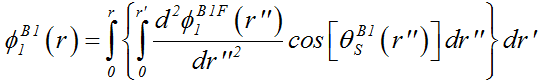
Have you derived somewhere the zeroth derivative of the curvature of the twisted mode shapes? or what is the formula that relates phi_1 with phi_1BF in Eq. (3.16)?
Thank you for the help.
Best regards,
Koen
Dear Koen,
The equation for phiB1_1 in terms of phiB1F_1 can be written by the double integral shown below. (Note the image uses a slightly different nomenclature from what is written in the report you reference–this equation was taken from the “Unofficial FAST Theory Manual” mentioned in the posts above". Note also that the rigid-body blade-pitch angle has been taken out of the equation, and is treated elsewhere in the code; that is, the twisted shape functions are not dependent on the blade-pitch angle.)
This double integral is implemented numerically within ElastoDyn. In general, this double integral cannot be written in closed form unless an analytical expression was provided for the blade structural twist, thetaB1_S (even then, an analytical calculation of the double integral would be difficult).
Best regards,
Dear Sir,
I am using the FAST v7 seismic module with the Bladed DLL controller for the monopile.
As an output of the simulations, I observed that the pitching moment of the blades increased almost 2.5 times, and the flapwise was about 1.1-1.2 times. Also, the edgewise moment was about 1.5 times in some cases.
So, to my surprise, the flapwise wise moments were not affected much. Instead, it was the edgewise moments and pitching moments. I also checked the tip-clearance values for the blade, but it didn’t show any change. So, if I can visualize the scene correctly, the blades are able to remain in the rotor plane and rather pitch about its axis. Also, it is bending in the plane of the rotor.
Now my task remains to delineate the reasons for the same, which I believe makes the discussions in the thread about structural pre-twist important. Should I check the forces/moments at various sections along the blades to further explain why only the edgewise/pitching moments are affected during a seismic event?
Or is it a modeling manifestation of the blade model that is leading me to such results?
I am fairly a beginner in understanding the details of blades. Hence, it would really mean if I can some direction to further investigate the problem at hand for me. Thanking You
Subham
On further reading of the posts in the same thread:
- If the torsional dofs of the blades aren’t modeled in FAST v7, how is the pitching moment evaluated in fast v7?
- Does it mean that the torsional effects of the blade do not reflect in fast v7? Won’t the pitching moment cause the blades to twist in FASTv7 ? In that case, will the values/time series of the local blade moments at blade nodes represent realistic values for blade design?
Thanks
Subham
Dear @Kashyap.Subham,
I’m not sure I understand your question. You refer to “pitching moment of the blades increased”, etc. But you haven’t said what you are comparing to.
Regarding your specific questions:
- You are correct that FAST v7 does not consider the torsional DOFs of the blades. Any pitching moment or force applied offset from the pitch axis will generate a moment about the pitch axis, but this moment will not twist the blade.
- Again, FAST v7 does not consider blade-twist DOFs. The pitching moment calculated will be accurate for situations where the torsion mode natural frequencies are much higher than the excitation frequencies (i.e., when the 1st torsion mode natural frequency is above about 9P or so).
Best regards,
Dear Sir,
The increase was noted in the case of the earthquake compared to the case without an earthquake.
Also, sir, how can I estimate the torsional modes of the blades? Are you hinting that the seismic response for the blades are inaccurate using FAST v7 seismic module? I do get an increase in the pitching moments during the earthquake.
Dear @Kashyap.Subham,
If you are modeling the NREL 5-MW baseline wind turbine, the torsion modes of that turbine are of high frequency. So, it is OK to neglect the torsion DOF of the blades and FAST v7 should be sufficiently accurate.
How do the flapwise and edgewise deflections compare for the cases with and without seismic loading? Flapwise and edgewise deflections will naturally effect the pitching moment because these deflections end up as moment arms to generate pitching moments from the flapwise and edgewise forces.
Best regards,
The figure shows the effect of earthquake loading on the chosen wind speeds (8m/s, 11.6 m/s, 16 m/s). The load factor is calculated by normalizing the average of above median extreme obtained with 10 simulations with earthquake by the extreme obtained without an earthquake. So, the effect of earthquake is more pronounced at the lower wind speeds, especially the edgewise (1.5 times) and the pitching moments (2.3 times).
I observed almost negligible rotor over-speed during the earthquake. Apart from this, the tower clearance too didn’t show any deviations during the earthquake. The figure above, to some extent, explains a few insights. The majority of the loads occur in the edgewise and the pitch-wise motions. I guess the blade bends in the plane with a twist. But, obviously, the twist isn’t taken into account in FAST v7.
I really wish I could have used beamdyn to confirm the claims above.
Is there a diagram that I can utilize to see how the flapwise/edgewise deflections increase the pitching moment?
Since the blade.dat file contains the sectional torsional stiffness, and fast calculates the pitching moment at each time step (due to pretwist/edgewise/flapwise motions), can I approximate the resultant twist at each time-step using the pitching moment?
Any clues/suggestions shall certainly help me. Thank You.
Subham
Dear @Kashyap.Subham,
I find the pitching moment harder to understand relative to the flapwise and edgewise moments. This is made more difficult when looking only at the extremes. How do the means and standard deviations of the pitching moment compare (considering that the extremes are likely related to the mean plus some multiple of the standard deviation)?
I was just speaking generically about the pitching moment depending not only on the direct aerodynamic pitching moment, but is also tied to the flapwise and edgewise deflections and associated forces. To understand the pitching moment, it may also help to plot these deflections and forces.
While some blade structural files in FAST v7 contain torsional stiffness, please note that the structural model of FAST v7 does not use these torsion inputs (these inputs are only used by the FAST-to-ADAMS preprocessor). I’m sure there is a way to estimate the twist caused by the pitching moment reaction load at each cross section, but I’ve not done this before as a post-processing step of FAST v7, so, I don’t really have anything to send you.
Best regards,
1 Like
Dear Sir,
Thank You for your time during the discussion. The seismic effects induced non-stationarity in the 10 min simulations. The means calculated for the coupled earthquake simulations will not adequately reflect the seismic effects. Hence, the idea was to capture the effects on the extremes, which will be useful for the ultimate limit states.
Adding to the comment on FAST v7 using the section torsional stiffness, do you mean that the pitching moment at each analysis node doesn’t incorporate the respective GJStff values? In that case how is the pitching moment evaluated? Is it independent of the structural properties of the blade/section?
Thanks
Dear @Kashyap.Subham,
Correct. The GJStff values are not used by the structural model of FAST v7. The blade is not a statically indeterminate structure, so, it is possible to calculate the sectional reaction loads without knowledge of the sectional properties. In the case of pitching moment, the moment is the integral along the blade of the applied moments and inertial moments and applied forces, weights, and inertial forces crossed with the moment arms, which involve the flapwise and edgwise deflections.
Best regards,
Dear Sir,
Thank you for the clarifications and insights into FAST.
The blade file lists the torsional stiffness, whose units are specified in Nm^2. Shouldnt it it Nm/rad?
Even the flapwise and edgewise stiffness units are defined to be Nm^2. Is this a valid unit for a stiffness quantity? Or is there something more to it than I can make out?
Thanks
Subham
Sir,
Can you help me visualize how the pitching moment is generated in FAST? I am having a really tough time trying to understand how flapwise and edgewise motions shall induce pitching moments.
I believe the total aerodynamic force acts at the aerocent which 0.25times the chord towards the leading edge, while the body pitches along the axis passing through the cog of the blade. Is the axis passing through the cog and the pitching axis same in FASTv7 Seismic Module?
Thanks
Subham
Dear @Kashyap.Subham,
The units as stated in Nm^2 are correct. These are cross-section stiffness values, e.g., as discussed in the following forum topic: FlpStff and EdgStff - #2 by Jason.Jonkman.
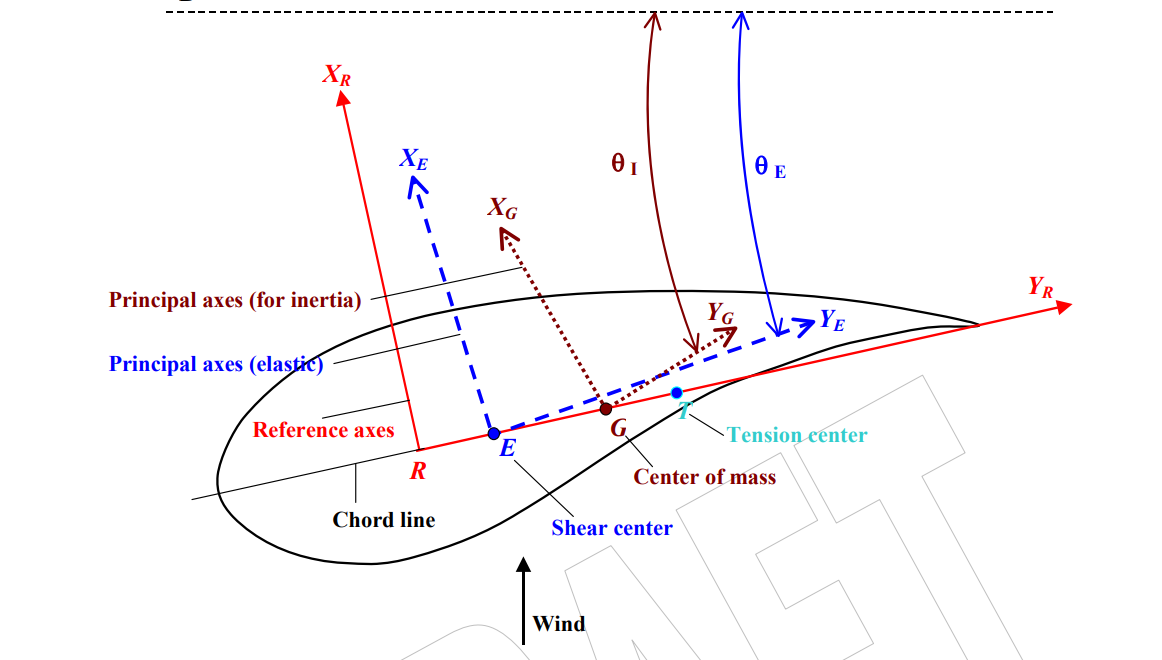
In FAST v7, the elastic axis and mass axis of the undeflected blade are aligned with the pitch axis, while the aerodynamic center may be offset from the pitch axis. The offset of the aerodynamic center from the pitch axis acts as a moment arm so that the aerodynamic loads applied at the aerodynamic center can generate pitching moments. Moreover, when the blade deflects flapwise, any force in the edgewise direction will create a pitching moment because the flapwise deflection acts as a moment arm; likewise, when the blade deflects edgewise, any force in the flapwise direction will create a pitching moment.
Best regards,
So the as per the figure (taken from bmodes documentation) points R and G coincide ? Apart from that aerodynamic centre is location at Aerocent-0.25, positive towards the trailing edge. What is the location the centre of mass for the aerofoil?
Thanks
Subham
Dear @Kashyap.Subham,
In FAST v7, points R, E, G, and T are all aligned with the pitch axis for the undeflected blade. And theta_E and theta_I are aligned (referred to as StrctTwst).
Regarding AeroCent used in FAST v7, here is my description (from: NREL 5MW Rotor Geometry - Wind & Water / Rotor Aerodynamics - NREL Forum):
AeroCent in FAST v7 is used to locate the reference point relative to the pitch axis for which aerodynamic (lift, drag, pitching) coefficients are defined. AeroCent in FAST v7 is defined as follows:
AeroCent = 0.25 - [ (fraction of chord from leading edge to actual pitch axis) - (fraction of chord from leading edge to aerodynamic coefficient reference point) ]
(The 0.25 in the equation above comes from FAST v7’s assumption that the pitch axis passes through 25% chord.)
Best regards,
Dear @Jason.Jonkman
It seems that ElastoDyn, same as FAST v7, does not have the ability to calculate torsional deformation. My team found in simulations using Bladed v4.3 (also modal method) that it had more than 5% effect on blade flapping results, even though the 1st twist natural frequency was well above 15P. I know BeamDyn can already calculate the results of torsional deformation, but why doesn’t ElastoDyn make the related improvement? What problems might be encountered when adding torsional degrees of freedom to the ElastoDyn code?
Best regards,
Dear @Cao.Yuming,
I agree that torsion can be important for modern wind turbine blades, but adding a blade torsion DOF to ElastoDyn is much more difficult than you’d expect. Some have attempted to capture blade torsion through modification of ElastoDyn or similar software such as Flex, and were not successful at obtaining an accurate responses. Simply adding a torsion mode on top of the existing flapwise and edgewise modes would not produce good results in most cases. To capture blade torsion properly, you must capture:
- Torsion-shear coupling, including offsets of the shear center from the pitch axis
- Possible couplings to other modes due to composite effects
- Nonlinear dynamics, including centrifugal stiffening of the torsion mode
NREL has not yet been funded to work on such improvements, but rather, has focused on introducing BeamDyn and resolving its known issues.
We have thought about adding a simple quasi-static torsion correction to ElastoDyn, e.g., by adding an elastic twist angle proportional to the pitch moment. We are still looking at ways to fund such an effort. While not highly accurate, this would be relatively simple to implement and may provide decent first-order effects of torsion.
Best regards,